
TRIAC dimmer light circuit with dual time constant

The Triac dimming light circuit utilizes a Triac as the main switching element, allowing for the control of the power delivered to a load, typically an incandescent bulb. The dual time constant behavior is achieved through the strategic selection of resistor and capacitor values, specifically R3 and C2. This arrangement allows for a rapid response to changes in the control signal, thereby reducing the lag time associated with the dimming process.
In this configuration, capacitor C1 charges and discharges through the resistors R2 and R3, alongside capacitor C2. The charge time of C2 is crucial as it influences the timing of the Triac's triggering point. By increasing the value of R3 and C2, the circuit can effectively manage the charge and discharge cycles, allowing for smoother transitions in light intensity. This is particularly beneficial in applications where precise control over lighting conditions is necessary, such as in theater lighting or mood lighting environments.
The circuit can be further optimized by selecting components that minimize thermal drift and ensure stable operation across varying temperatures. Additionally, incorporating snubber circuits may protect the Triac from voltage spikes, enhancing the reliability of the dimming function. Overall, this Triac dimming light circuit design presents an effective solution for mitigating lag and improving light transition performance in dimmable lighting applications.In order to solve the lag and light transition phenomena, it can use the Triac dimming light circuit shown in the figure with dual time constant. The circuit increases R3, C2 resistor-capacitor network, and the reducing charge on capacitor C1 can get promptly complement through C2, R2, R3 circuit, it can effectively reduce the lag and lighting transitions a..
🔗 External reference
Related Circuits
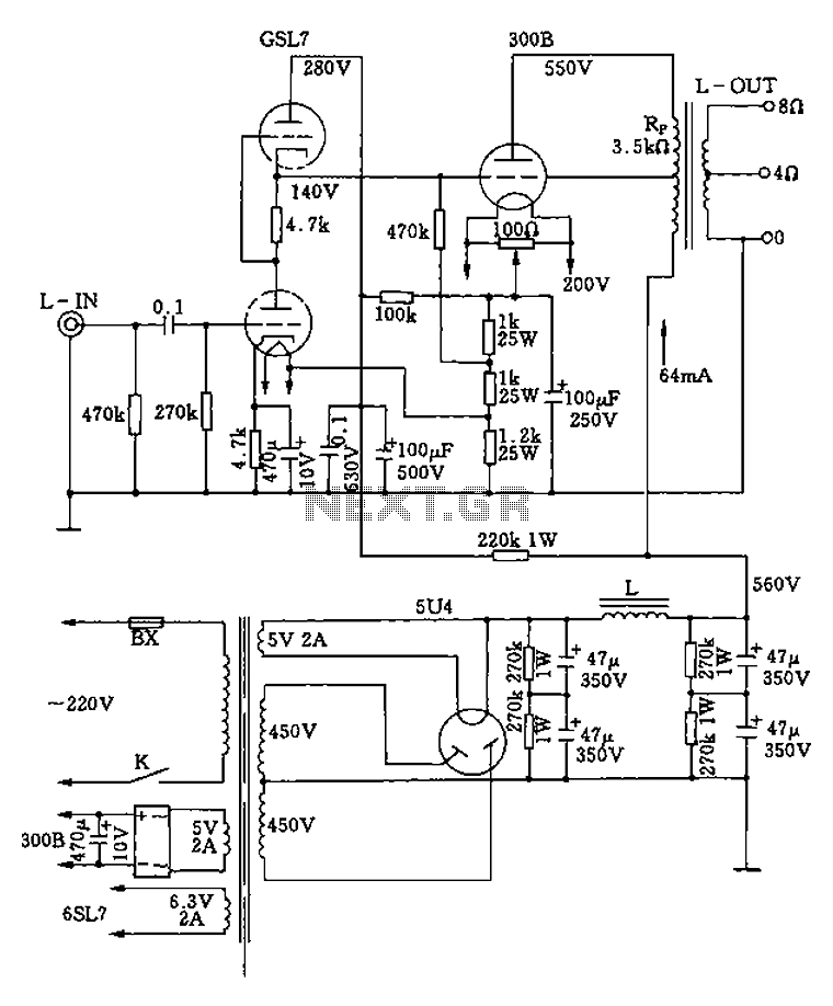
The 300B tube single-ended Class A amplifier circuit is as follows: The 300B tube single-ended Class A amplifier is a high-fidelity audio amplification circuit that utilizes a 300B vacuum tube as the primary amplification element. This design is characterized by...
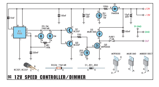
This circuit can function as a speed controller for a 12V motor with a continuous rating of up to 5A or as a dimmer for a 12V halogen or standard incandescent light. The circuit utilizes a pulse-width modulation (PWM) technique...
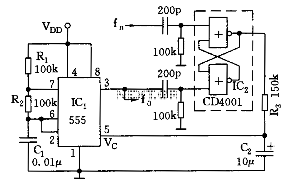
The circuit illustrated consists of a 555 timer along with resistors R1 and R2, and capacitor C1, forming a composition-controlled multivibrator. The oscillation frequency is influenced not only by the RC time constant but also by the adjustment of...
Direct measurement circuit for soil content, assessing various parameters such as moisture, salinity, nitrogen, and pH to enhance soil quality for diverse agricultural crops. This electronic measuring circuit facilitates rapid and accurate testing of soil conditions and informs fertilization...
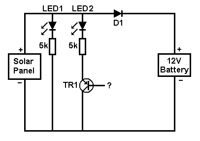
A small solar panel is used to maintain a 12V car battery. The panel provides approximately 75mA of current to the battery under full sunlight conditions. The described circuit employs a solar panel specifically designed for battery maintenance applications. The...

This circuit is designed as a 10-channel LED sequencer with the addition of solid-state relays for controlling AC lamps. The circuit operates using relays. The relay depicted in the diagram is a Radio Shack 3 amp unit (part no....