
G0MRF 29.45 MHz Receiver Project

The iSTAR project aimed to incorporate an Amateur Radio payload designed to facilitate educational opportunities and promote interest in radio communications among enthusiasts and students. The payload's integration into the VEGA launcher represented a strategic move to leverage space technology for educational purposes, aligning with AMSAT-UK's mission to advance amateur radio and satellite communications.
The VEGA launcher, known for its versatility and reliability, was chosen as the vehicle for this initiative, emphasizing the potential of small satellite missions in educational outreach. The iSTAR payload was intended to provide practical hands-on experience for students and educators, fostering skills in radio operations, satellite communications, and STEM (science, technology, engineering, and mathematics) disciplines.
The proposal included detailed plans for the payload's design, operational capabilities, and potential applications. By utilizing the VEGA launcher, AMSAT-UK aimed to demonstrate the feasibility of deploying amateur radio technology in space, thereby inspiring a new generation of radio amateurs and engineers.
Overall, the iSTAR initiative reflects a commitment to innovation in education and the promotion of amateur radio as a valuable tool for learning and exploration in the context of space technology.In 2007/8 AMSAT-UK put considerable work into a proposal to the European Space Agency (ESA) to place an Amateur Radio payload on the mass dummy on the maiden flight of the VEGA launcher. Known as iSTAR (Integrated Suite for Teaching and Amateur Radio) it was planned to use. 🔗 External reference
Related Circuits
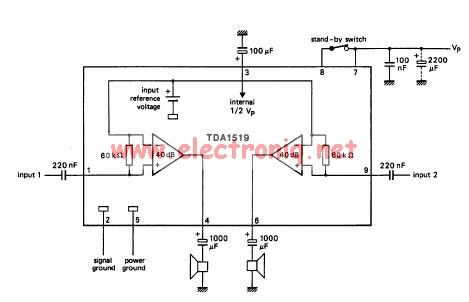
The TDA1519 circuit can deliver 2x6 watts of output power. The TDA1519 is an integrated class-B dual output amplifier housed in a 9-lead single in-line (SIL) plastic medium power package, primarily developed for car radio applications. The TDA1519 amplifier is...
This active antenna schematic can be used to frequency range from 10 KHz to 100 MHz. The length of the Antenna can be between 0.5 to 1 meter long. The power consumption is 20-30mA. More: Use the shortest possible...
FM Beacon Broadcast Transmitter (88-108 MHz). This circuit will transmit a continuous audio tone on the FM broadcast band (88-108 MHz), which could be used for remote control or security purposes. The FM Beacon Broadcast Transmitter operates within the frequency...
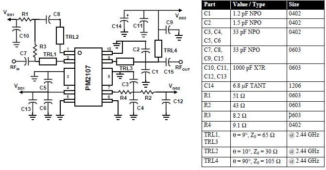
This RFIC amplifier operates in the 2400 MHz ISM band and features a two-stage design that is off-chip matched to ensure optimal performance across various applications. Powered by a 5-volt supply, the PM2107 can deliver 1 watt of saturated...
This project and your efforts will provide you with a 0.55...3 watt input to easily 10 watt output. The two linear amplifiers are meant for use with QRP SSB/CW/FM/AM transmitters on the amateur bands 15 and 17 meters can...
This transmitter is PLL controlled and the frequency is very stable and can be programmed digitally. The transmitter will work from 88 to 108 MHz and the output power is up to 500mW. With minor changes the frequency can...