
FM PLL transmitter 88-108MHz with PIC16F870

The value of C3 will set the VCO range. The large value of C3 the wider will the VCO range be. Since the capacitance of the varicap is dependent of the voltage over it, the capacitance will change with changed voltage. When the voltage change, so will the oscillating frequency. In this way you achieve a VCO function. The oscillator is made to work as "Voltage Controlled Oscillator" VCO. To control the frequency a synthesizer circuit LMX 2306 has been added. The PLL circuit has a pickup coil (L2) connected to pin 6. This coil should be put close to the L1 coil for picking up some of the oscillating energy. The PLL in the LMX2306 will then use this frequency to regulate the VCO and lock it to desired frequency. The regulating system also need an external reference crystal. In this case I use 12.8 MHz.
At pin 2 of MX2306 you will find a PLL filter to form the Vout which is the regulating voltage of the VCO. The PLL try to regulate the Vout so the oscillator keeps the frequency locked to desired frequency. The desired frequency is programmed into the PIC EEPROM and is clocked into the synthesizer (LMX2306) at power up. At pin14 of the synthesizer you have a control output. At this output you will find the reference frequency for testing. (I must warn you because the signal is not symetrical in shape. The positive pulse are only a few microsecond so you will have difficult to see it at oscilloscope.) I solved it by connecting it to a 74HC4020 (14-stage Binary Counter) to pin 10 Clock input. At Q0 (pin 9) you will have a symmetrical square wave with half frequency since the circuit is a counter. At Q1 pin 7 it will be divided by 4, see datasheets for more info. Here you find another HF transistor and it is working in class C. The resistor R1 and the resistor Re2 set the DC current. In this case I found that 9.1k will give good output power and so the same with 150. If you wish to increase the power Re2 should be lower. You can add another 150 ohm resistor parallel. In the table below I show you the output power with different voltages and values of resistor Re2. I advice you not to run this transmitter with to high output power. The transistor I use is a small one and tends to get hot. I advice you to run the unit from 0 - to 200mW. At 500mW the transistor will be in pain...*smiling* At the output you will find a T network. This "filter" will match the antenna impedance to the transmitter output stage. You have two variable capacitors 60pF to tune the transmitter for best performances. The antenna I used I a 1/4 wave whip antenna (wire) about 75cm long. This type of antenna is smaller but not so good performance as a dipole. With a dipole you will be able to transmitter much longer distance. How long can I transmit? That is a very difficult question because the environment affect the transmitting distance very much. In a city environment with concrete buildings the transmitter will send maybe 200m. I an open filed it will transmit 2000m. I did a filed test and with 70mW output power into the "bad" whip antenna placed indoors I could transmit 200-300m out into a park with no problem.
The described transmitter design incorporates a Phase-Locked Loop (PLL) architecture, facilitating stable frequency generation and programmability within the FM broadcast band of 88 to 108 MHz, with potential adjustment capabilities extending from 50 to 150 MHz. The core of the oscillator is a Colpitts configuration utilizing a BC817 transistor (T1), which is suitable for high-frequency applications. This oscillator is complemented by an LC tank circuit composed of an inductor (L1) and capacitors (C1, C2, C3) along with a varicap diode (BB139) to achieve frequency modulation.
The varicap diode's capacitance varies with the applied voltage, enabling dynamic frequency modulation. The voltage-controlled oscillator (VCO) function is achieved through careful selection of C3, which determines the range of frequencies generated by the oscillator. To maintain frequency stability, a synthesizer IC, the LMX2306, is employed, featuring a feedback mechanism through a pickup coil (L2) that samples the oscillating energy from L1. This feedback allows the PLL to lock the VCO to the desired frequency, with an external 12.8 MHz crystal serving as a reference.
The PLL filter at pin 2 of the LMX2306 regulates the output voltage (Vout), which directly influences the VCO frequency. The desired frequency is stored in the EEPROM of a microcontroller (PIC) and is loaded into the synthesizer during power-up, ensuring that the system is ready for operation without additional user input.
For frequency testing, a control output at pin 14 of the LMX2306 provides a reference frequency. To enhance the visibility of the output signal, a 74HC4020 binary counter is employed, which generates a symmetrical square wave at a reduced frequency, facilitating easier observation on an oscilloscope.
The output stage of the transmitter operates in Class C mode, with resistors (R1 and Re2) determining the DC current and consequently the output power. It is advised to limit the output to a maximum of 200mW to prevent overheating of the BC817 transistor. The output stage is matched to the antenna through a T-network filter, which includes two variable capacitors for fine-tuning the matching process.
A 1/4 wave whip antenna, approximately 75 cm in length, is utilized for transmission, although a dipole antenna would provide superior performance for longer distances. Transmission range is heavily influenced by environmental factors, with estimates suggesting a range of 200 meters in urban settings and up to 2000 meters in open fields. Practical tests have demonstrated effective transmission distances of 200-300 meters under various conditions with reduced output power.This transmitter is PLL controlled and the frequency is very stable and can be programmed digitally. The transmitter will work from 88 to 108 MHz and the output power is up to 500mW. With minor changes the frequency can be set from 50 to 150 MHz. The main oscillator is based around the transistor T1. This oscillator is called Colpitts oscillator and it is voltage controlled to achieve FM (frequency modulation) and PLL control. T1 should be a HF transistor to work well, but in this case I have used a cheap and common BC817 transistor.
The oscillator needs a LC tank to oscillate properly. In this case the LC tank consist of L1 with C1, C2, C3, and the varicap BB139. The coil is parallel with C1 and C2 which are in serial . The same with the varicap and C3. You can think that L is parallel with [ (C1//C2) + (Varicap//C3)] The value of C3 will set the VCO range. The large value of C3 the wider will the VCO range be. Since the capacitance of the varicap is dependent of the voltage over it, the capacitance will change with changed voltage. When the voltage change, so will the oscillating frequency. In this way you achieve a VCO function. The oscillator is made to work as "Voltage Controlled Oscillator" VCO. To control the frequency a synthesizer circuit LMX 2306 has been added. The PLL circuit has a pickup coil (L2) connected to pin 6. This coil should be put close to the L1 coil for picking up some of the oscillating energy. The PLL in the LMX2306 will then use this frequency to regulate the VCO and lock it to desired frequency.
The regulating system also need an external reference crystal. In this case I use 12.8 MHz. At pin 2 of MX2306 you will find a PLL filter to form the Vout which is the regulating voltage of the VCO. The PLL try to regulate the Vout so the oscillator keeps the frequency locked to desired frequency. The desired frequency is programmed into the PIC EEPROM and is clocked into the synthesizer (LMX2306) at power up.
I will below explain how to program the EEPROM for different frequencies. At pin14 of the synthesizer you have a control output. At this output you will find the reference frequency for testing. (I must warn you because the signal is not symetrical in shape. The positive pulse are only a few microsecond so you will have difficult to see it at oscilloscope.) I solved it by connecting it to a 74HC4020 (14-stage Binary Counter) to pin 10 Clock input. At Q0 (pin 9) you will have a symmetrical square wave with half frequency since the circuit is a counter.
At Q1 pin 7 it will be divided by 4, see datasheets for more info. Here you find another HF transistor and it is working in class C. The resistor R1 and the resistor Re2 set the DC current. In this case I found that 9.1k will give good output power and so the same with 150. If you wish to increase the power Re2 should be lower. You can add another 150 ohm resistor parallel. In the table below I show you the output power with different voltages and values of resistor Re2. I advice you not to run this transmitter with to high output power. The transistor I use is a small one and tends to get hot. I advice you to run the unit from 0 - to 200mW. At 500mW the transistor will be in pain...*smiling* At the output you will find a T network. This "filter" will match the antenna impedance to the transmitter output stage. You have two variable capacitors 60pF to tune the transmitter for best performances. The antenna I used I a 1/4 wave whip antenna (wire) about 75cm long. This type of antenna is smaller but not so good performance as a dipole. With a dipole you will be able to transmitter much longer distance. How long can I transmit? That is a very difficult question because the environment affect the transmitting distance very much. In a city environment with concrete buildings the transmitter will send maybe 200m. I an open filed it will transmit 2000m. I did a filed test and with 70mW output power into the "bad" whip antenna placed indoors I could transmit 200-300m out into a park with no problem.
🔗 External reference
Related Circuits
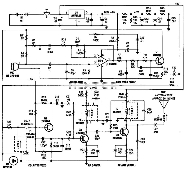
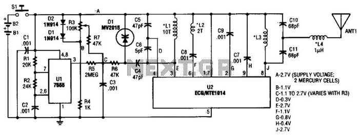
This tracking transmitter consists of four distinct subassemblies: a free-running multivibrator, a transmit switch, an audio-tone generator, and an FM transmitter. The multivibrator, which produces a pulse width with a pulse separation of 1500 ms, is built around Q1...
A simple USB FM transmitter that can be used to play audio files from an MP3 player or computer on a standard VHF FM radio by connecting it to a USB port. The circuit does not require any coils...
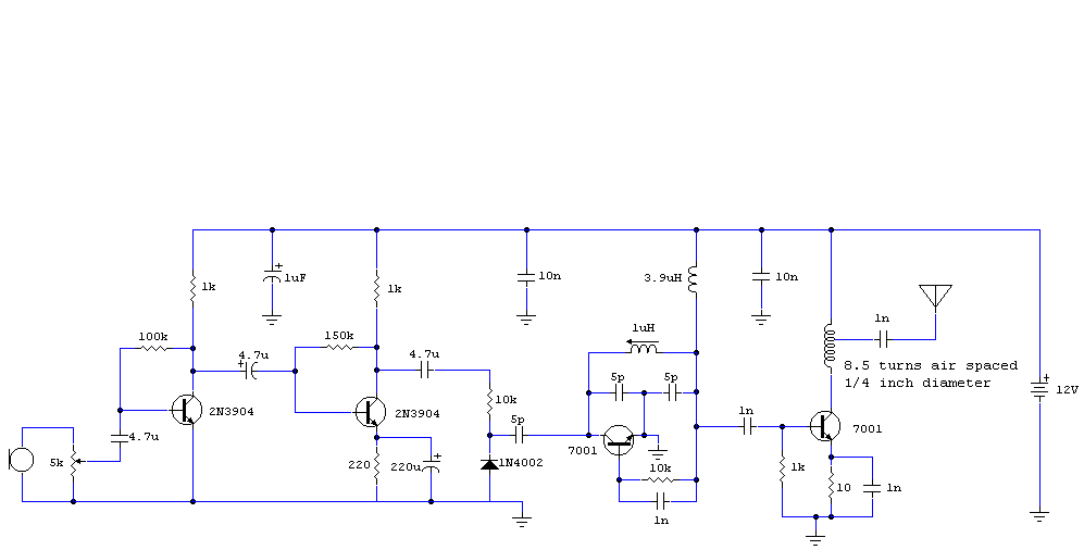
The audio circuit described is a microphone utilizing two 2N3904 transistors as the audio preamplifier. The audio/microphone gain is adjustable via a 5k preset potentiometer. The circuit employs a Colpitts oscillator for frequency generation, which is free-running and operates...
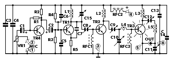
This is a small but quite powerful FM transmitter having three RF stages incorporating an audio preamplifier for better modulation. It has an output power of 4 Watts and works off 12-18 VDC which makes it easily portable. It...
This transmitter can be utilized for multiple applications. An INS8048L microprocessor produces various codes based on keypad inputs. These codes are modulated onto a 40-kHz carrier frequency. Additionally, Q1 drives infrared LEDs LED1 and LED2. The transmitter circuit primarily consists...
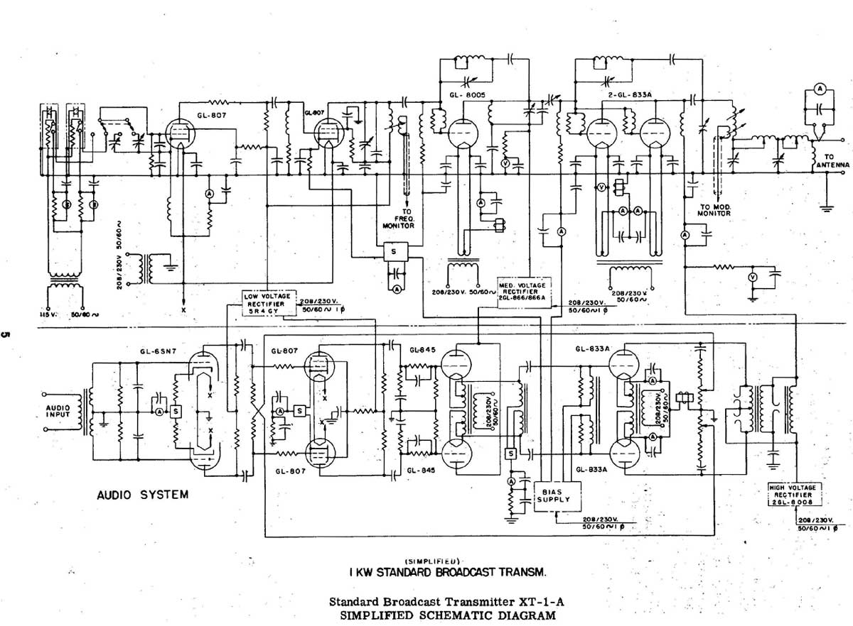
In the past, when AM radio was dominant, significant resources were allocated to the development of transmitting equipment. The GE BTA-25 transmitter from that era exemplified this commitment, featuring a robust construction. During a repair of the Harris MW-50A...