
Game roller or chase circuit

The circuit utilizes a 555 timer in astable mode to create a continuous pulse signal. The frequency of these pulses can be adjusted by selecting appropriate resistor and capacitor values connected to the timer. The output of the 555 timer is connected to the clock input of the 7493 binary counter, which counts the pulses and provides a binary representation of the count. The 7493 has four flip-flops, allowing it to count from 0 to 15 in binary (0000 to 1111).
The binary output from the 7493 is then directed to the 74154 decoder/demultiplexer. This device takes the 4-bit binary input and activates one of its 16 outputs, corresponding to the binary value received. The active output goes low while the others remain high, ensuring that only one output is enabled at any time.
The single current-limiting resistor (R3) is strategically placed in series with the LEDs. This configuration is efficient as it minimizes component count and ensures that only the active LED receives current, thereby preventing damage from excessive current flow. The design is particularly useful in applications where visual indicators are needed, allowing for a clear representation of the binary count through the illumination of the corresponding LED.
In summary, this circuit demonstrates a practical application of digital counting and decoding techniques, utilizing the 555 timer, 7493 counter, and 74154 decoder to create a simple yet effective LED display system. The design ensures reliable operation with minimal components while providing clear visual feedback through the LEDs.The 555 timer produces a rapid series of pulses whenever switch SI is open. These pulses are counted in groups of 16 and converted into binary form by the 7493 and applied to the 74154 (a l-of-16 decoder/demultiplexer) wired so that each of its 16 output lines goes low sequentially and in step with the binary count delivered by the 7493. When the switch is closed, only one LED remains on Only one current limiting resistor (R3) is used for all the LED"s since only one is on at any one time.
Related Circuits

The first amplifier circuit is a bird phone. In this circuit, the electret microphone (MIC1) is mounted in the neck of a large plastic funnel. The amplifier, built around an MC34119, is then placed outside of the funnel with...
This 5-volt Switch Mode Power Supply circuit utilizes an integrated circuit (IC) from National Semiconductor, which specializes in the production and design of ICs for switch-mode power supply applications. The 5-volt Switch Mode Power Supply (SMPS) circuit is designed to...
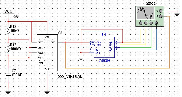
This tutorial explores a common digital concept using the NI Multisim software environment. It examines a four-bit counter that uses a 555 timer IC to generate the clock signal. This tutorial takes less than 30 minutes to complete and...
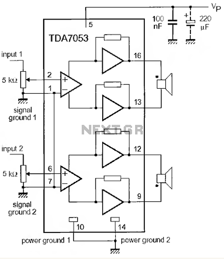
This is a 1-watt stereo audio amplifier circuit utilizing the TDA 7053 integrated circuit from Philips. It is specifically designed for battery operation, delivering 1 watt per channel from a 6V DC supply. The circuit operates optimally between 6V...

A step-down transformer converts AC 220V to a lower voltage. A diode bridge rectifier and filter capacitor provide a direct current (DC) output, which fluctuates with variations in the grid voltage. A resistive voltage divider is used for sampling....
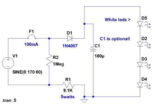
If the AC supply is 220 volts, which resistor should be replaced and with which one? Since 220V is twice that of 110V, the resistance value needs to be doubled accordingly. It is suggested to replace the 9.1kΩ resistor...