
Game-scoring Display ScreenCircuit

The game-scoring display circuit is designed to facilitate real-time scoring for games, allowing players to track their scores accurately. The circuit can be divided into four main functional blocks.
1. **Add/Subtract Scoring Input Circuit**: This section receives input signals that determine whether the score should be increased or decreased. Typically, this circuit may utilize push-button switches or other input devices that generate a high or low signal corresponding to scoring actions. The signals are processed to determine the direction of scoring—addition or subtraction.
2. **Add/Subtract Scoring Circuit**: This block processes the input from the scoring input circuit. It utilizes logic gates or an arithmetic logic unit (ALU) to perform the necessary calculations based on the input signals. The output from this circuit will represent the current score, which can be a positive or negative integer depending on the scoring actions taken.
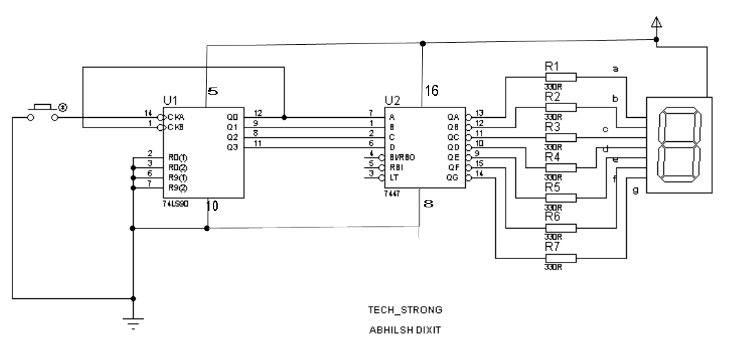
3. **Counting-Decoding Display Circuit**: The output from the scoring circuit is then fed into a counting-decoding circuit, which translates the numerical score into a format suitable for display. This may involve the use of binary-coded decimal (BCD) encoders or similar components that convert the score into a format that can be displayed on a digital screen, such as seven-segment displays or LCDs. This circuit ensures that the score is visually represented in a clear and understandable manner.
4. **Reset Circuit**: To facilitate game resets, a reset circuit is included. This circuit allows the score to be cleared and set back to zero, preparing the display for a new game. The reset function can be triggered by a dedicated button or automatically at the start of a new game session.
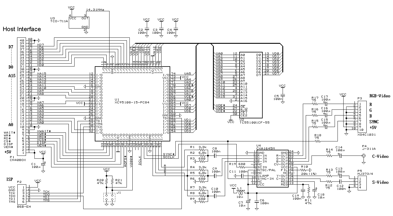
Overall, the game-scoring display screen circuit is essential for providing immediate feedback to players regarding their scores, enhancing the gaming experience through accurate and efficient score management. Each component of the circuit plays a crucial role in ensuring reliable operation and user interaction.Game-scoring display screen circuit diagram is shown as in the above picture. The circuit is composed of add/subtract scoring input circuit, add/subtract scoring circuit, counting - decoding display circuit and reset circuit.. 🔗 External reference
Related Circuits
This is a simple display controller. It can be controlled with a small microcontroller, such as MCS51, 68HC11, Z80, AVR, and others. Several years ago, I found an article that controlling a TV with only a PIC microcontroller, and...

The circuit is designed to connect in parallel with a telephone, displaying the dialed number using DTMF (Dual Tone Multi-Frequency) signaling. It can also show the number dialed from the receiving party's phone, making it useful for capturing numbers...
The lab project involves a BCD counter and a 7-segment display using the CD4510BMS presettable BCD Up/Down Counter. The objective is to count from 32 to 84, rather than the default range of 00 to 99. The current setup...
Connecting a LCD display to your personal computer is an easy job. Displaying data from your PC to a LCD can be proven very exciting, so give it a try and build your own today! In this article, we...
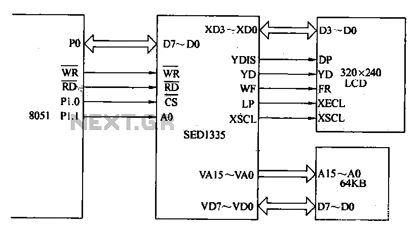
The MCS-51 series single-chip interface circuit 8051 is utilized to control the SED1335 35 dot matrix LCD display. This controller can manage up to a 640x256 dot matrix LCD display for both graphics and character representation, with the capability...
This project allows for the display of digits from 0 to 9 on a seven-segment display while counting the number of people entering a room. A counter IC, the 7490, is utilized alongside a BCD to seven-segment decoder IC,...