
GP display controller

The display controller described serves as an interface between a microcontroller and a video display device, such as an RGB monitor or a television. The circuit comprises three integrated circuits (ICs), which are selected for their compatibility with a variety of microcontrollers, including MCS51, 68HC11, Z80, and AVR families. The choice of these ICs is crucial as they facilitate the generation of the necessary synchronization signals and manage the color data output to the display.
The first IC typically functions as a video signal generator, responsible for producing the necessary timing signals and modulating the color information. The second IC may serve as a buffer or level shifter to ensure that the signals are appropriately conditioned for the display device. The third IC often acts as a controller, interfacing directly with the microcontroller to receive data and commands while also managing the overall operation of the display system.
The simplicity of the design is highlighted by the reduced number of interconnections, which minimizes potential points of failure and makes assembly easier. Each component is chosen for its availability and commonality, ensuring that builders can source parts easily from standard electronics suppliers, such as Aki. The schematic diagram accompanying the description illustrates the connections between the microcontroller and the display controller ICs, providing a clear guide for assembly.
This display controller is particularly suited for educational projects or hobbyist applications, where the goal is to demonstrate video signal synthesis and control without the complexity of more advanced systems. It allows users to explore the fundamentals of video signal processing and display technology in a straightforward manner.This is a simple display controller. It can be controlled with a small microcontroller, such as MCS51, 68HC11, Z80, AVR and others. Several years ago, I found an article that controlling a TV with only a PIC micorcontroller, and I surprised to it. It is very interesting to attempt to synthesize video signal with a micorcontroller. However, it is not suitable for practical use because the microcontroller is occupied in synthesizing video signal, it cannot process any other operation.
Therefore, this technic can be applied to a toy at the best. It is required a display controller to contorl the video monitor, so I designed and built a simple display controller for RGB monitor and TV monitor. This is the circuit diagram for display controller. It is very simple, isn`t it? It is using only three ICs, number of wires is reduced compared from previous project. Each part in this project is not special, so that whole parts will be found in Aki 🔗 External reference
Related Circuits
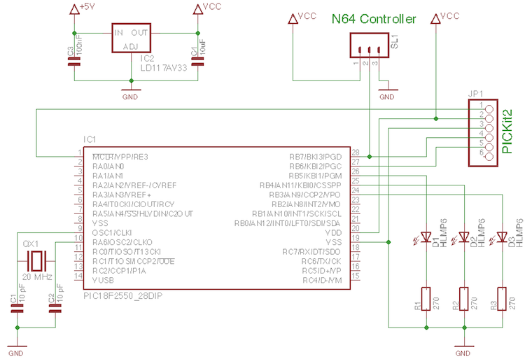
A few old N64 controllers were found, and the idea is to use them to control other devices. This document outlines the detailed steps taken to achieve this. A PIC microcontroller was utilized, although the code can be adapted...
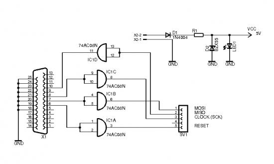
The brain of the robot is composed of an Atmel Tiny2313 microcontroller. This MCU features In-System Programming, allowing programming of its memory using a low-cost programmer. A simple programmer connects to the parallel port and is described in the...
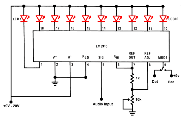
This is a simple audio sound level LED display circuit diagram. The circuit is entirely based on a single integrated circuit, the LM3915 from National Semiconductor. The LM3915 is a monolithic integrated circuit that displays the audio sound level...
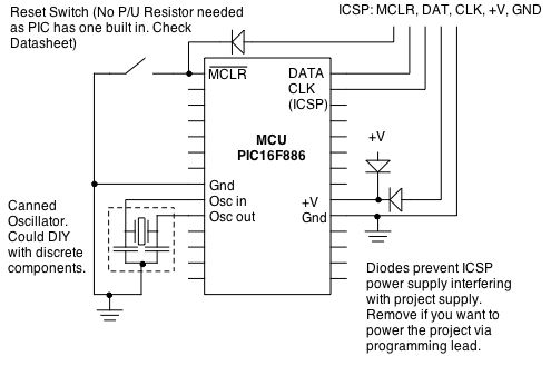
Microcontrollers (MCUs) are versatile integrated circuits that enhance the functionality of electronics, robotics, and other projects. However, they... Microcontrollers (MCUs) serve as the central processing unit in a variety of electronic applications, offering programmable control that allows for complex functionalities...
In industrial PLC applications, one of the older yet simpler methods of displaying numeric information involves utilizing one or more 7-segment numeric displays connected to an output card of a PLC. While it is feasible to construct such a...
A tachometer can be constructed using the TC9400 in frequency-to-voltage (F/V) mode to convert frequency information (RPM) into a linearly proportional voltage. This voltage can then be compared to one of several comparators (in this example, using eight). The...