
Gate Deep Oscillator

To build it, particular experience in radio-frequency assembly is required. First of all, remember to keep all connections as short as possible; otherwise, problems may arise above 50 MHz. Coils are built as shown later using a 5-pin DIN plug.
The circuit operates by utilizing a BF245 or K161 FET as the active component, which is configured in a common-source configuration to provide the necessary gain and oscillation. The frequency of oscillation can be adjusted by changing the inductance of the coil connected to the circuit. This is typically achieved through a variable inductor or by using a switchable arrangement of fixed inductors.
The oscillator is powered by a suitable DC voltage source, typically within the range of 9V to 15V, ensuring that the FET operates within its specified limits. The output can be taken from the drain of the FET, where a buffer stage may be added if necessary to match the impedance of the load or for further processing of the signal.
The 100 microA meter serves as a tuning indicator, allowing the user to monitor the current flowing through the circuit, which correlates with the oscillation frequency. This feature is particularly beneficial for tuning the output to specific frequencies required for testing various radio components.
The use of a metal case is crucial for shielding the oscillator from external electromagnetic interference, which can affect performance, especially at higher frequencies. The double-sided vetronite board serves as the substrate, with one side dedicated to the ground plane, reducing noise and improving stability.
When assembling the circuit, it is essential to minimize the length of the connections to prevent inductive and capacitive coupling that could distort the oscillation frequency, especially above 50 MHz. The coils should be constructed according to specific dimensions and winding techniques to ensure the desired inductance values are achieved.
Overall, this variable oscillator circuit is a valuable tool for radio frequency experimentation and development, providing flexibility in frequency generation and reliable performance when properly constructed and housed.It`s just a variable oscillator based on a bf245 or k 161 fet. By changing the coil it can generate frequency between 0.5 and 300 MHZ. this circuit is useful to test radio circuit such as filter, receiver, transmitter and so on . It can be use for coil tuning thanks to the 100microA meter .It must be placed in a metal case but I`ve used a double sided vetronite board, one for ground. To build it , is requested particular experience in radio-frequency assembling . First of all remember to put as short as possible all connections or you`ll have problems over 50 MHZ. .Coils are build as shown later using a 5 pins DIN plug . The cent 🔗 External reference
Related Circuits
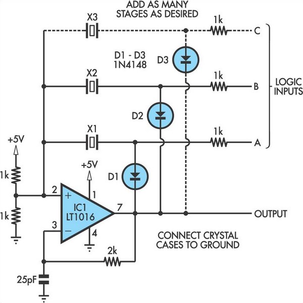
This oscillator circuit allows crystals to be electronically switched by logic commands. To understand the circuit, it is helpful to initially disregard all crystals and consider all diodes as shorts while their associated 1kΩ resistors are treated as open....
An oscillator is an amplifier with a feedback loop from output to input. The Barkhausen criteria state that for oscillation to occur, the product of the gains around a loop must be equal to or greater than unity, and...
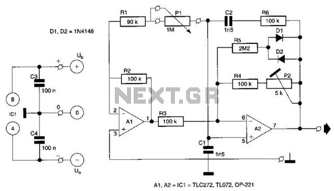
This circuit utilizes a single potentiometer to control a frequency range from 300 Hz to 3000 Hz. A FET operational amplifier is employed at stages A1 and A2. The upper frequency limit is dictated by the gain-bandwidth product of...

This is a design circuit for a low distortion crystal oscillator. The circuit generates a sine wave with low phase noise and distortion, allowing for the use of a crystal with less than 1mV dissipated across it. The crystal...
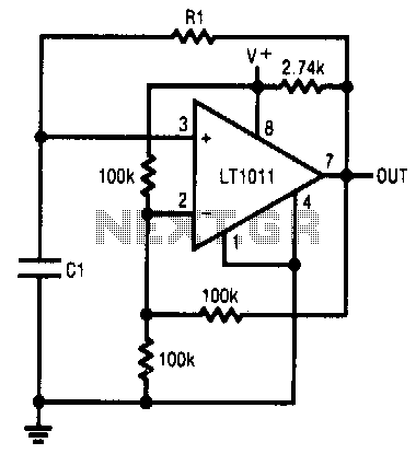
This simple RC oscillator utilizes a medium-speed comparator with hysteresis and feedback through R1 and C1 as timing elements. The frequency of oscillation is theoretically independent of the power supply voltage. Additionally, the comparator swings to the supply rails...

The term VCXO refers to a Voltage Controlled Crystal Oscillator. The frequency of this oscillator can be fine-tuned by varying the control voltage. VCXO clock generators are utilized in a range of applications, including digital telecommunications. VCXO circuits are essential...