
Variable Wein Bridge Oscillator Circuit

The circuit design incorporates a single potentiometer, which serves as a variable resistor, allowing for the adjustment of frequency within the specified range. The operational amplifiers (op-amps) used in this circuit are field-effect transistor (FET) types, known for their high input impedance and low noise characteristics, which are advantageous in frequency modulation applications.
At stage A1, the FET op-amp amplifies the input signal, with the gain set by the feedback network that includes the potentiometer. This stage is crucial for adjusting the amplitude of the output signal, ensuring that it remains within the optimal range for further processing.
Stage A2 continues the amplification process, further refining the signal. The gain-bandwidth product of the op-amps is a critical parameter, as it defines the maximum frequency at which the op-amps can effectively amplify the signal. In this circuit, the upper frequency limit of 3000 Hz is determined by this product, ensuring that the circuit can operate effectively across the entire frequency range.
Overall, the design emphasizes the importance of selecting appropriate components and configurations to achieve the desired frequency response. The use of a potentiometer for tuning provides flexibility, while the choice of FET op-amps ensures high performance and reliability in signal processing. This circuit uses a single potentiometer to time a 300- to 3000-Hz range. A FET op amp is used at A1 and A2. The upper frequency limit is determined by the gain-bandwidth product of the op amps.
Related Circuits
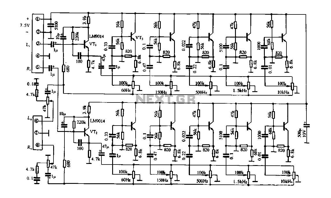
Figure 4-33 illustrates a circuit configuration that includes a common amplifier along with analog inductive circuits. In this setup, the transistor in the analog inductive circuit is utilized, and an increase in the bias resistor enhances circuit stability. A...
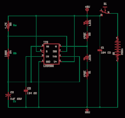
The LM311 is a comparator that operates from a single 5V supply or dual supplies, with an input current of 150 nA and an output drive capability of 50 V and 50 mA. It features a TTL-CMOS compatible output....
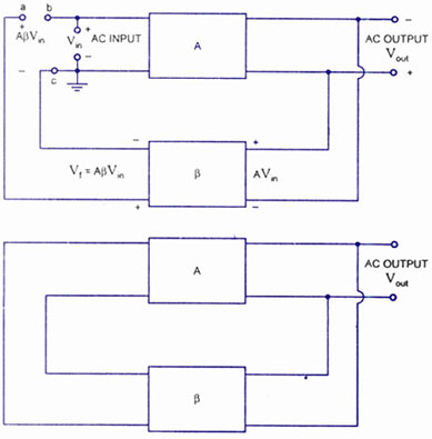
A feedback amplifier with a closed-loop gain, Af, greater than unity can be achieved through the use of positive feedback. This condition also fulfills the phase requirement, leading to the operation of an oscillator circuit. An oscillator circuit generates...
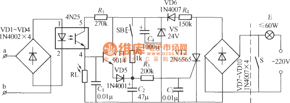
The diagram illustrates an automatic lighting control circuit activated by a telephone. At night, when the telephone rings or the user picks up the receiver, the light turns on. If the telephone stops ringing (when no one is listening)...
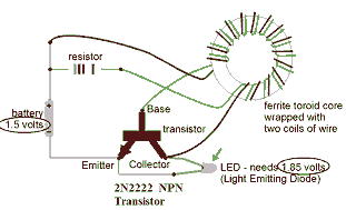
This circuit is known as the Joule Thief. For those unfamiliar with it, an image of the circuit is provided. The Joule Thief is a minimalist circuit designed to extract usable voltage from a low-voltage power source, such as a...
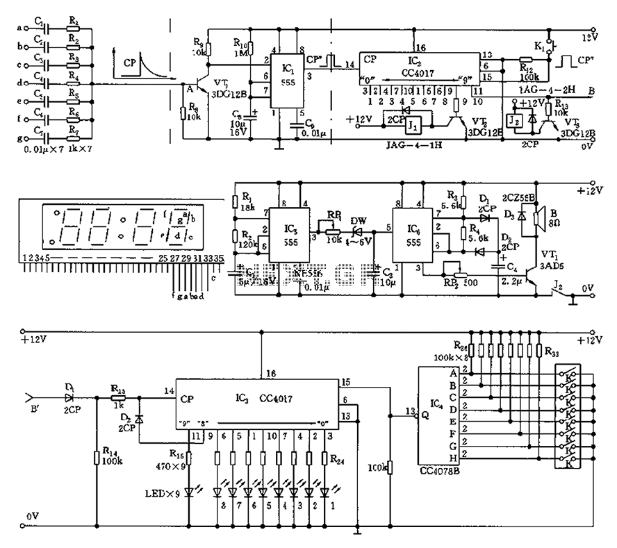
This circuit is primarily designed as a timely reminder system for monitoring individuals on duty who may fall asleep. It features a detection circuit that processes minute signals. As the LED digital electronic timing clock displays the minute, the...