
GE/MACOM MASTR-III VHF Station

The conversion of the GE/MACOM MASTR-III Group 2 radio model involves several critical steps to ensure compatibility with the 144-148 MHz amateur radio band. First, it is essential to verify the functionality of the original frequencies to avoid complications during the conversion process. The use of a service monitor with a spectrum analyzer is recommended for precise tuning, allowing for real-time observation of signal characteristics.
For the soldering aspect of the modification, a high-quality soldering iron is crucial, as surface mount components require careful handling and precision. The recommended soldering iron should have a fine tip to accommodate the small pads on the circuit board, and the use of fine diameter solder will facilitate better control during the soldering process.
The programming of the repeater is conducted via a DB-9 RS-232 connection, which allows for the adjustment of audio levels and power output. Proper configuration of the software is vital; hence, it should be confirmed that the MASTR-III mode is selected to prevent any risk of bricking the system module. The editing of parameters should be approached methodically, ensuring that all adjustments are accurately reflected in the system.
The adjustment of DIP switches in the synthesizer modules plays a crucial role in achieving the desired frequency output. Understanding the differences between Group 1 and Group 2 configurations is necessary for successful conversion. The output frequency calculation is straightforward but must be accurately executed to ensure proper operation within the amateur radio spectrum.
In conclusion, the conversion process is intricate and requires attention to detail, proper tools, and a thorough understanding of the radio's architecture. Following the outlined steps will facilitate a successful transformation of the GE/MACOM MASTR-III Group 2 radio into a functional amateur radio repeater.This article provides conversion instructions for radio model # GE/MACOM MASTR-III Group 2 (150. 8-174 MHz) Repeater or Base, Combination Number SXS, to allow it to perform adequately in the 144-148 MHz range. Please be aware that this document is currently a work in progress, which may contain several omissions and typographical errors.
Continue r eading at your own risk. Make sure the station to be converted is in good working order on its original frequencies before attempting conversion to Amateur Radio use. Note that a Fault light on the Receiver Synthesizer Module may be the result of a missing External Reference Source.
Verify in programming software and set source to internal if that is the case. To tune the Receiver Front End module properly, I recommend using a service monitor with a spectrum analyzer (HP-8920 series, IFR-1600S or similar). It is possible to use a signal generator and a frequency selective RF voltmeter, or a service monitor with simultaneous generate and receive, but these are not as easy as you can`t see where the peaks and dips are.
Full Modification requires a great deal of surface mount soldering. You will need a quality soldering iron. I use a Weller with an 800 degree tip `R`, along with fine diameter solder, 0. 015 inch, and fine tweezers. Connection to the repeater is done with a straight through DB-9 RS-232 cable. Connect either to the Data Port on the front of the repeater or the DB-9 connection on the rear of the interface board. You will use this application to set the repeat audio levels and transmitter power output. It can also help diagnose the repeater to a degree with the ability to convey that one or more modules are malfunctioning.
M2E. BAT and M3. BAT are designed to change the station operating parameters, such as CTCSS tones and hang times, and in the case of the MASTR-III, the operating frequencies. It is important that the software be in MASTR-III mode. Programming the repeater with the software in M2e mode may inadvertently brick the System Module requiring replacement.
Start the software with M3. BAT. Be sure the screen looks like above with the `MASTR-III Control Shelf Programming` at the top. This software has some compatibility issues, as it is an older DOS based program. A PIII tablet with a USB to RS-232 adapter and WinXP would not program, but a PII laptop with a hardware based serial port and WinXP would. Once that is done highlight the file you will be editing and hit F2. Edit the data to your new operating parameters. Use F9 over any field to get a description of what it adjusts. For some reason `space` is not an allowed character when programming the Morse Code ID, so don`t pull your hair out.
Once done save the data by pressing F10 and then F1 and confirm the over-write. The Fault LEDs on the Transmitter and Receiver synthesizer modules should now be lit as the PLLs are no longer able to lock. There may be a slight flicker on the LEDs as the System Module will be attempting to reset the synthesizers until the fault clears.
Remove the Transmitter Synthesizer Module from the T/R frame. Using a small straight jeweler`s screwdriver or `greenie` and a flashlight, adjust the DIP switches through the access hole in the cover of the module to the following configuration: Please note that the Group 1 (136 - 151 MHz) Synthesizer generates high side Local Oscillator injection where as the Group 2 (150. 8 - 174 MHz) generates low side. The output frequency of the Receiver Synthesizer Module will be: Receive Frequency + 21. 4 MHz, i. e. 146. 04 MHz + 21. 4 MHz = 167. 44 MHz. Remove the Receiver Synthesizer Module from the T/R frame and remove the top cover. Flip the card over and remove the 6 screws that hold the RF shielding sub frame around the VCO section.
If you want full Group 1 conversion, replace the Group 2 components to the G1 specifications as found in the manual. A few component changes are all that is n 🔗 External reference
Related Circuits
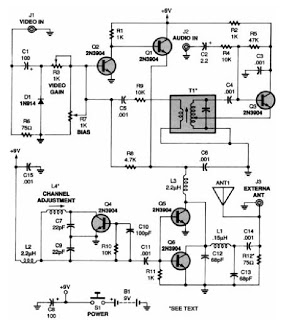
The 555 timer oscillator section can be removed and replaced with a preferred microphone modulating circuit to transmit audio to a television set, requiring minimal tuning. The schematics available on Schematics Depot were sourced from the internet and are...
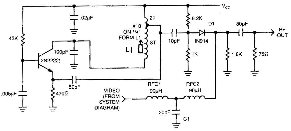
This circuit utilizes an oscillator (2N2222) and a diode (D1) as a nonlinear mixer. The frequency is determined by a slug in L1. RFCl, C1, and RFC2 create a low-pass filter designed to pass video signals while blocking RF...
A low-power VHF TV transmitter is an essential tool for video enthusiasts, allowing the transmission of signals from a VCR to any television in a home or backyard setting. This device enables the convenience of watching movies by the...
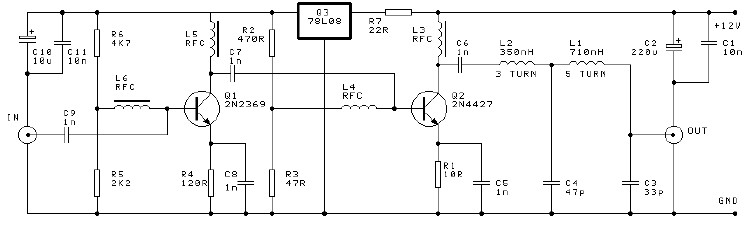
This project involves a 250mW RF power amplifier circuit. It is designed to amplify the output of approximately 7mW wideband FM transmitters to a final output level of about 250mW. The circuit utilizes a simple two-transistor VHF power amplifier...

The mixer is equipped with two stereo phono inputs and two stereo line-level inputs, along with a single stereo mixing channel. It includes a microphone input and a stereo main output with adjustable gain. The general circuit diagram displays...
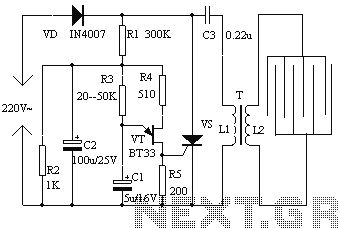
The electronic fly disinfestation system is a simple and effective device designed to eliminate flies using electrical means. The apparatus, as depicted in Figure 1, operates on 220V mains power supplied directly through a rectifier. It utilizes a relaxation...