
VHF Beacon
The circuit modification involves taking out the 555 timer oscillator, which is typically used for generating pulse-width modulation signals, and integrating a microphone modulating circuit instead. This modification allows for the transmission of audio signals, such as voice, directly to a television set.
To implement this, a suitable microphone circuit must be selected that can effectively convert sound waves into an electrical signal. Common choices include electret condenser microphones or dynamic microphones, which can be configured to work with a preamplifier to boost the signal strength before modulation.
The microphone output needs to be modulated to ensure compatibility with the transmission requirements of the television set, which may involve amplitude modulation (AM) or frequency modulation (FM) techniques. The choice of modulation will depend on the specific characteristics of the television's audio input.
Once the microphone circuit is integrated, the overall circuit will require tuning. This tuning process may involve adjusting the gain of the microphone preamp, selecting appropriate filter components to eliminate noise, and ensuring the modulation frequency aligns with the television's audio input specifications.
In conclusion, by replacing the 555 timer oscillator with a microphone modulating circuit, it is possible to create a system that facilitates audio transmission to a television set. Careful selection of components and tuning will enhance the performance and clarity of the transmitted audio.You can cut away the 555 timer oscillator part and add your favorite microphone modulating circuit to transmit voice over to your tv set with a little tuning. Schematics in Schematics Depot were found on the internet and assumed to be in public domain. Contact webmaster if the copyright holder wants them pulled for any reason. 🔗 External reference
Related Circuits

Integrated circuits (ICs) that were previously too costly for hobbyists are now more affordably priced. An example is the AD8099 from Analog Devices, which is available for only a few pounds. The AD8099 is a very fast operational amplifier...
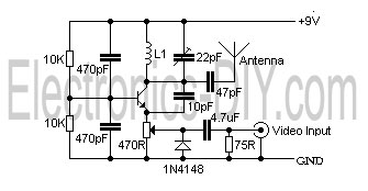
This is a simple video transmitter capable of transmitting signals up to 50 meters. It can be utilized with cameras or other video sources and allows viewing on VHF channel analog televisions. The video transmitter operates on a supply...
This stage begins at the VHF antenna. The incoming VHF RF signal is preamplified and filtered and presented as the "RF" signal to the ADE and Double Balanced Mixer (DBM). The mixer also accepts the Local Oscillator's output (before...
At VHF, both the 1/4-wavelength monopole and the 5/8-wavelength monopole antennas are widely used. The VHF 5/8-wavelength (144 MHz) vertical monopole has long held the reputation of providing about a 3-dB gain advantage over the 1/4-wavelength vertical monopole. The...
This amplifier has VHF (very high frequency) and UHF (ultra high frequency) response, and it can be used as a receiver booster, for example. Here is the schematic. The described amplifier is designed to enhance signal reception in the VHF...
The beacon is currently utilizing a simple Continuous Wave (CW) keying QRSS3 at a frequency of 10140.020 kHz, with a power output of 20 milliwatts. The PIC program used is PicBeacon developed by Ik2pcb. The concept for this beacon...