
General Infrared Remote Controlled Relay

This relay circuit provides a versatile method of controlling devices using infrared remote signals. The primary component, the phototransistor, acts as a light sensor that detects the modulated infrared signals emitted by the remote control. The common emitter configuration amplifies the detected signal, allowing for the effective filtering of unwanted noise. The filtering capacitor, C2, plays a critical role in ensuring that only the desired high-frequency signals are processed, which is essential for maintaining the integrity of the relay control.
The operational amplifier IC1 is central to the circuit's performance, with its gain set to 220 times, allowing for significant amplification of the incoming signal. This high gain ensures that even weak signals from the infrared remote can be translated into a usable output for the relay. The negative-feedback network comprising resistors R5 and R2 stabilizes the gain and improves the linearity of the amplifier's response, ensuring that the output remains consistent across varying input levels.
The half-rectifier voltage doubler circuit is designed to convert the amplified AC signal into a usable DC voltage that can energize the relay coil. The choice of a germanium diode in this application is particularly advantageous due to its lower forward voltage drop compared to silicon diodes, resulting in improved sensitivity and responsiveness of the circuit. This is especially important in applications where the infrared signal may be weak or where rapid response times are required.
The relay, represented by RLA, is utilized to control a secondary circuit or device, enabling the operation of various electronic loads based on the infrared signals received. The common-emitter switch configuration, consisting of transistor TR2 and capacitor C2, allows for efficient switching of the relay, providing a reliable method of controlling the connected load.
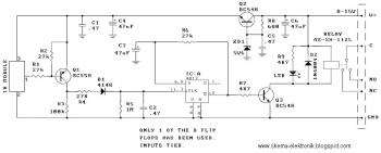
In summary, this relay circuit is an effective solution for interfacing infrared remote controls with various electronic devices, utilizing robust design principles to ensure reliable operation in the presence of potential interference.This relay circuit is controlled by almost any type of infrared remote controller. This circuit works on assumption that almost all remote controller use high frequency modulated infrared light. By filtering out un-modulated or low frequency modulated signal, this circuit will be able to remove any interference from ambient infrared light coming f
rom other sources such as sun light, soldering iron, or incandescent lamps. Here is the schematic diagram of the circuit: This circuit employs a phototransistor which is configured in common emitter amplifier. The C2 does the filtering out of the unmodulated or low frequency signals. The negative-feedback network is formed by R5 an R2. This negative-feedback network set the closed-loop voltage gain of IC1 at 220 times. The amplified output signal from IC1 pin 6 is fed to a half-rectifier-voltage double circuit (D2, C5 and D1).
Since the germanium diode has lower forward voltage drop, the germanim diode is used rather than silicon diode. It increases the sentivity of this circuit. The relay RLA coil is controlled by a simple common-emitter switch which is formed by TR2 and C2. We aim to transmit more information by carrying articles. Please send us an E-mail to wanghuali@hqew. net within 15 days if we are involved in the problems of article content, copyright or other problems.
We will delete it soon. 🔗 External reference
Related Circuits
In this circuit, the 555 timer is utilized in an innovative manner as a voltage-controlled switch. The widely used NE555 can perform effectively in various applications. The 555 timer, a versatile integrated circuit, is commonly employed in timer, delay, pulse...
All modern infrared (IR) remote control devices generate a continuous coded stream of pulses at 37.9 kHz when any button on the device is pressed. These IR pulses are received and decoded by a compatible device, such as a...
This circuit below shows a teleremote circuit that enables the switching on and off of appliances through telephone lines. The teleremote circuit utilizes a telephone line as a medium for controlling electrical appliances from a distance. The primary components...

CoolCAD Electronics, LLC is a CAD and custom electronics design firm that specializes in satisfying non-mainstream electronic design applications. CoolCAD Electronics, LLC operates as a comprehensive design firm focusing on computer-aided design (CAD) and bespoke electronic solutions. The company emphasizes...
This circuit is designed to disrupt infrared (IR) remote signals, allowing users to override volume settings on a stereo, change TV channels, or create general interference. Key components include a ceramic capacitor, an electrolytic capacitor, a resistor, a battery,...
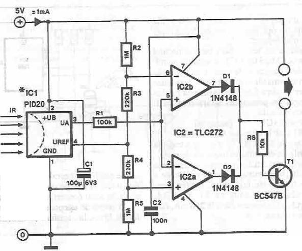
This infrared detector circuit utilizes the PID20 integrated circuit manufactured by Siemens, which converts thermal radiation into electrical impulses. It includes an operational amplifier and several electronic components. The output signal at pin 3 is compared to a reference...