
General-Purpose Preamp

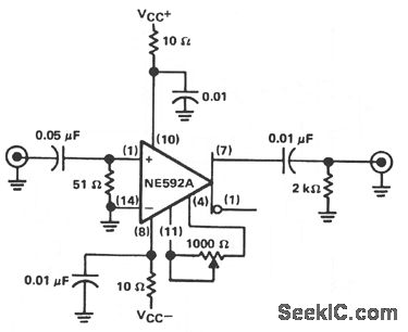
This amplifier circuit is designed for versatility in audio and video applications, leveraging a gain configuration that allows for easy adjustment through the feedback resistor (Rf). The expression for voltage gain, approximately 1 + (Rf / Rs), indicates that the gain can be tailored by selecting appropriate resistor values, where Rs represents the source resistance.
The bandwidth of the amplifier is a critical parameter that varies with the gain setting. Generally, as the gain increases, the bandwidth decreases, adhering to the trade-off principle known as Gain-Bandwidth Product. In practical applications, this amplifier can achieve a bandwidth in the range of several MHz, making it suitable for high-frequency audio and video signals.
When Rf is set to 5.1 kOhm, the resulting gain of 10 (20 dB) is indicative of the amplifier's capability to significantly amplify input signals. This gain setting is particularly useful in scenarios where moderate amplification is required without compromising the integrity of the signal.
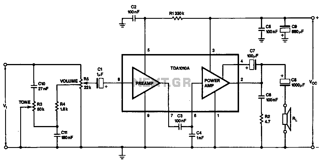
To implement this amplifier in a circuit, it is essential to consider the power supply requirements, input and output impedance matching, and thermal management to ensure optimal performance. Proper layout and grounding techniques should be employed to minimize noise and interference, which is critical in high-fidelity audio and video applications. The selection of additional components, such as bypass capacitors and feedback capacitors, may further enhance the stability and performance of the amplifier across its operational bandwidth. This amplifier is useful for audio and video applications. Gain is set by Rf and the voltage gain of this amplifier is approximately 1 + i//560, where R/vs, in ohms. Bandwidth depends on gain selected, but typically it is several MHz. R/= 5.1 KOhmhm, which produces a gain of 10 (20 dB) voltage. 🔗 External reference
Related Circuits
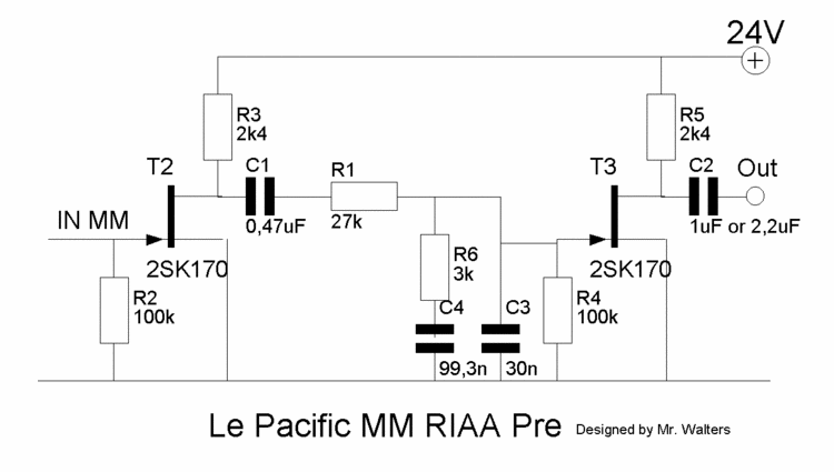
This document describes a DIY build of the Boozhound Laboratories JFET Phono Preamplifier constructed on a stripboard. The BHL preamp is primarily based on the Le Pacific RIAA phono preamplifier circuit. The construction utilizes brown polypropylene capacitors sourced from...
The circuit provides a voltage gain of 20 ±0.1 dB within a frequency range of 500 kHz to 50 MHz. The low-frequency response of the amplifier can be enhanced by increasing the value of the 0.05 µF capacitor connected...
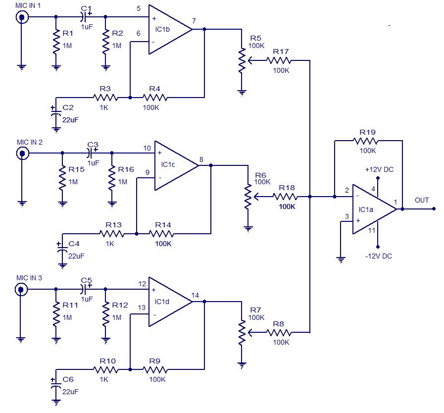
The circuit presented is a three-input microphone mixer and preamplifier utilizing the LM348 integrated circuit. The LM348 is a high-gain, internally compensated quad operational amplifier featuring a class AB output stage. It has a very low input supply current...
This preamplifier has a low output impedance, and is designed to drive long cables, allowing you to listen to a remote music source without having to buy expensive screened cables. The very low output impedance of around 16 ohms...
This monolithic IC, class-B audio amplifier circuit is a 6-W car radio amplifier for use with 4-ohm and 2-ohm load impedances. The monolithic integrated circuit (IC) described is designed to function as a Class-B audio amplifier, specifically tailored for...
The first half of the circuit (IC1a) features an input sensitivity of 3 mV and includes a frequency correction network consisting of capacitors C5, C3, and resistors R6 and R8. The bass signal from the phono input is amplified,...