
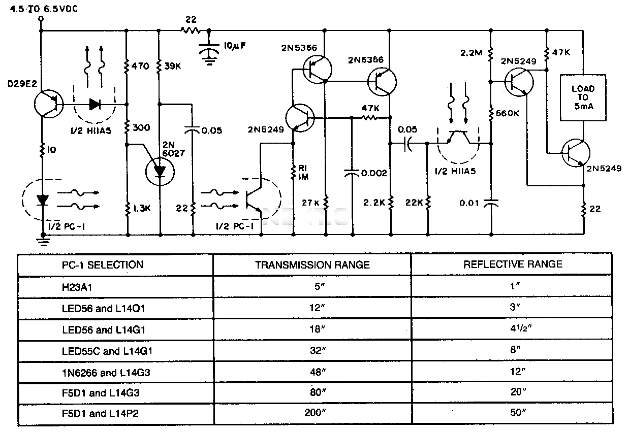
General purpose rf detector

The circuit is designed to facilitate the monitoring and testing of transmitters and modulated signals by providing both a direct current (DC) output and an optional audio output. The DC output can be connected to a meter, allowing for the measurement of voltage levels associated with the transmitted signals. This is particularly useful for assessing the performance of the transmitter and ensuring that it operates within specified parameters.
The audio output serves as an additional feature that enables the user to hear the transmitted signals, making it easier to evaluate modulation quality and signal clarity. This is especially beneficial in scenarios where auditory feedback is necessary for troubleshooting or calibration.
In applications where field strength measurement is required, the circuit can be adapted to function as a field strength meter. By connecting an appropriate antenna and adjusting the circuit parameters, it can provide real-time feedback on the strength of the transmitted signal, aiding in the optimization of transmitter placement and performance.
Overall, the circuit is versatile and can be employed in various testing and monitoring scenarios, making it an essential tool for engineers and technicians working with radio frequency (RF) systems. Its dual output capabilities enhance its functionality, allowing for comprehensive analysis of transmitter performance and signal integrity.This circuit provides a dc output to a meter and an audio output (if necessary) for checking transmitters or modulated signals. It can be used also as a field strength meter or transmitter monitor.
Related Circuits

The alarm can be utilized for various applications, including frost monitoring and room temperature monitoring. In its quiescent state, the circuit consumes only a few microamperes, allowing a 9 V dry battery (PP3, 6AM6, MN1604, 6LR61) to potentially last...
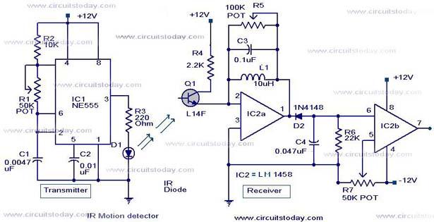
Infrared (IR) Motion Detector Circuit featuring a motion detector alarm and an infrared sensor. The circuit diagram and its operation are provided in detail. The infrared (IR) motion detector circuit is designed to detect motion within a specified range and...
A wideband RF detector is being designed, utilizing a series of resonant LC tanks spaced between 5 to 10 MHz apart, with an exception of 1 MHz spacing from 9 MHz onwards. The design of a wideband RF detector incorporating...
This simple and economical infrared model train detector circuit is designed specifically for hobbyists who want to incorporate a smart sensor to detect trains on their model railway track. The schematic diagram illustrates a straightforward configuration comprising an infrared...
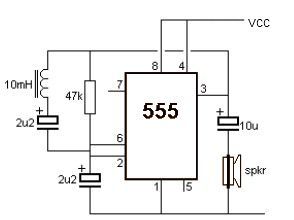
This metal detector electronic project schematic circuit is designed using a simple 555 timer integrated circuit. The schematic circuit requires few external electronic components. The metal detector circuit utilizes the 555 timer IC in an astable mode configuration, which generates...
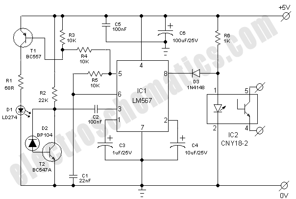
In applications requiring long-range operation with infrared (IR) light sources and high system reliability, pulsed-mode operation of the IR source is essential. Enhanced operational reliability is achieved through synchronous detection of the photodetector current, as implemented in this circuit....