
Infrared Motion Detector Circuit-IR motion sensor circuit with motion detector alarm

The infrared (IR) motion detector circuit is designed to detect motion within a specified range and trigger an alarm when motion is detected. The core components of this circuit include an infrared sensor, a microcontroller or comparator, a power supply, and an alarm output device such as a buzzer or LED.
The infrared sensor operates by emitting infrared light and detecting the reflection of that light from objects within its field of view. When a person or object moves within this range, the sensor detects the change in the reflected infrared light and sends a signal to the microcontroller or comparator.
The microcontroller processes the signal from the infrared sensor. If motion is detected, it activates the alarm output. The alarm can be configured to be a sound (buzzer) or light (LED), depending on the application requirements. The circuit may also include additional features such as sensitivity adjustment and delay timers to prevent false alarms from minor movements.
Power supply considerations are critical for this circuit. Typically, a battery or DC power source is used to provide the necessary voltage and current to the components. Proper voltage regulation may be incorporated to ensure stable operation of the circuit.
The schematic representation of the IR motion detector circuit will include the layout of the infrared sensor, the connections to the microcontroller or comparator, the alarm output configuration, and the power supply connections. The design should also indicate the values of any resistors, capacitors, or other passive components used to fine-tune the circuit's performance.
Overall, this infrared motion detector circuit is suitable for various applications, including security systems, automatic lighting control, and energy-saving devices, making it a versatile solution for detecting motion in a defined area.Infrared (IR) Motion Detector Circuit with motion detector alarm and infrared sensor.The motion sensor circuit diagram and working is given in detail.. 🔗 External reference
Related Circuits
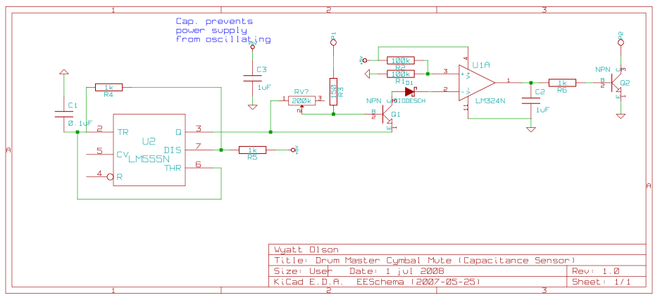
This page contains various small circuits created over time. Some circuits are trivial, while others are more complex, but all are intended to be useful for a variety of projects. Most include both the schematics and the source (KiCad)...

FIG M is a variable speed motor control for the opening and closing of a wicket gate. It features an electric governor. The system is activated by a power switch (SA) located on the front grid, and a toggle...

A simple PWM inverter circuit utilizes the SG3524 integrated circuit. This PWM inverter is designed for a 12V input, providing a 220V output with a maximum output power of 250 watts. The output power can be extended further. The described...
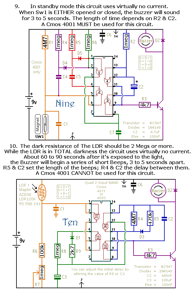
This document outlines a selection of small self-contained alarm circuits. Each alarm's main features are detailed on the circuit diagram. They are designed to have a very low standby current, making them suitable for battery operation. Each pair of...
Some time ago, a media center box was created to replace a DVD player, satellite receiver, VCR, and PlayStation 2 with a single device. A Core 2 Duo processor system successfully replaced all these electronic devices. However, a remote...
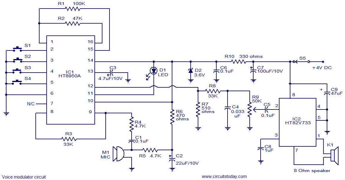
This is a versatile voice modulator circuit utilizing the HT8950A IC from Holtek Semiconductors. The IC can generate seven upward or downward frequency steps based on the input voice at a rate of 8 Hz. Additionally, it features two...