
Geomagnetic Field Detector circuit

This oscillator circuit operates based on the principle of detecting variations in the Earth's magnetic field using a ferrite rod and coil assembly. The ferrite rod serves as a magnetic core, enhancing the inductance of the coil wound around it. The coil is sourced from an old Medium Wave receiver, which is re-purposed to serve as the sensing element for the oscillator.
To assemble the circuit, a small magnet is affixed to one end of the ferrite rod. This magnet interacts with the Earth's magnetic field, and any movement of the ferrite rod will induce changes in the magnetic flux through the coil. These changes will produce variations in the oscillator's frequency, which can be heard as an audible note when tuned to a medium wave commercial station.
Proper screening is critical to the performance of this oscillator. The circuit is enclosed in a plastic box that is internally padded with copper wires. These wires should run parallel to the ferrite rod and be grounded at a single point to minimize electromagnetic interference and enhance the sensitivity of the oscillator.
A trimmer capacitor is included in the circuit to allow for fine-tuning of the oscillator frequency. A small access hole is provided in the enclosure, enabling adjustment of the capacitor using a plastic screwdriver, which prevents any potential short circuits or interference from metal tools.
For the transistor component of the circuit, the BC337 is recommended, although it can be substituted with the 2N2369A, which is an American equivalent. This transistor functions as an amplifier within the oscillator circuit, converting the oscillations produced by the coil into a signal that can be heard through a speaker or headphone.
Overall, this simple oscillator circuit offers a practical application for detecting variations in the Earth's magnetic field, making it an interesting project for electronics enthusiasts and those interested in magnetism.This basic oscillator will detect the Earth magnetic field. The ferrite rod and coil are taken from an old Medium Wave receiver and a small magnet is glued at one end. Tune to a medium wave commercial station until you hear a beat note. Any movement of the ferrite rod will produce an audible note that depends on the prevailing Earth magnetic field.
Screening is essential. Use a plastic box padded, on the inside, with copper wires running parallel to the rod and grounded in one place only. A small hole is made in the box in order to adjust the trimmer capacitor with a plastic screwdriver. An American equivalent to the BC337 could be the 2N2369A but I did not try it out. 🔗 External reference
Related Circuits
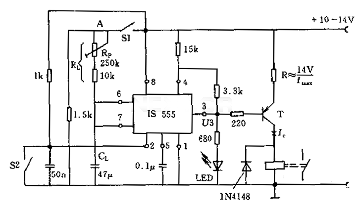
The circuit for the photoelectric switch S1 functions as a control switch for the luggage room light. In its closed operating state, the voltage is positive. If S2 is closed, irrespective of the state of S1, the output terminal...
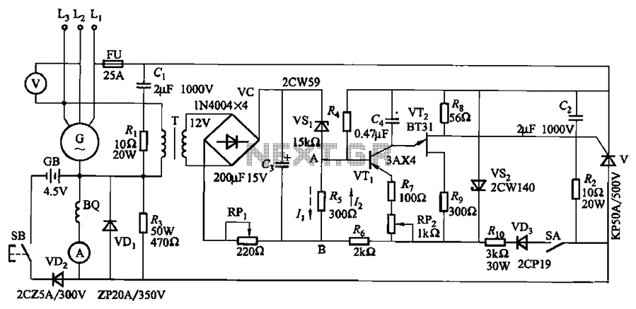
The circuit depicted in Figure 7-32 is designed for an excitation device capable of handling a terminal voltage of 400V and a capacity of less than 75kW for synchronous generator motors, enabling automatic adjustment of excitation. When the generator...
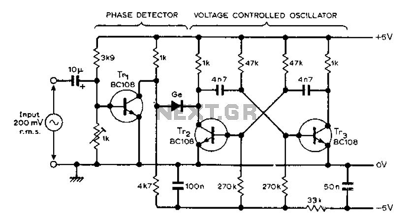
The circuit MVBR utilizes a traditional two-transistor configuration along with other components to create a simple phase-locked loop (PLL). The transistor TR1 and diodes function as a logic gate, activating during half periods of the input waveform of the...
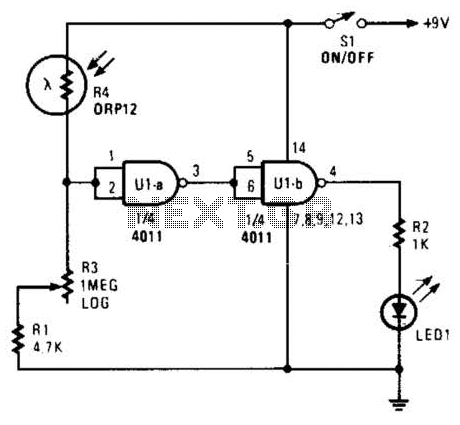
Two gates of a 4011 IC are utilized as a comparator. When the resistance of R4 decreases, the voltage at pins 1 and 2 increases, resulting in a logic zero at pin 3. This causes pin 4 to go...
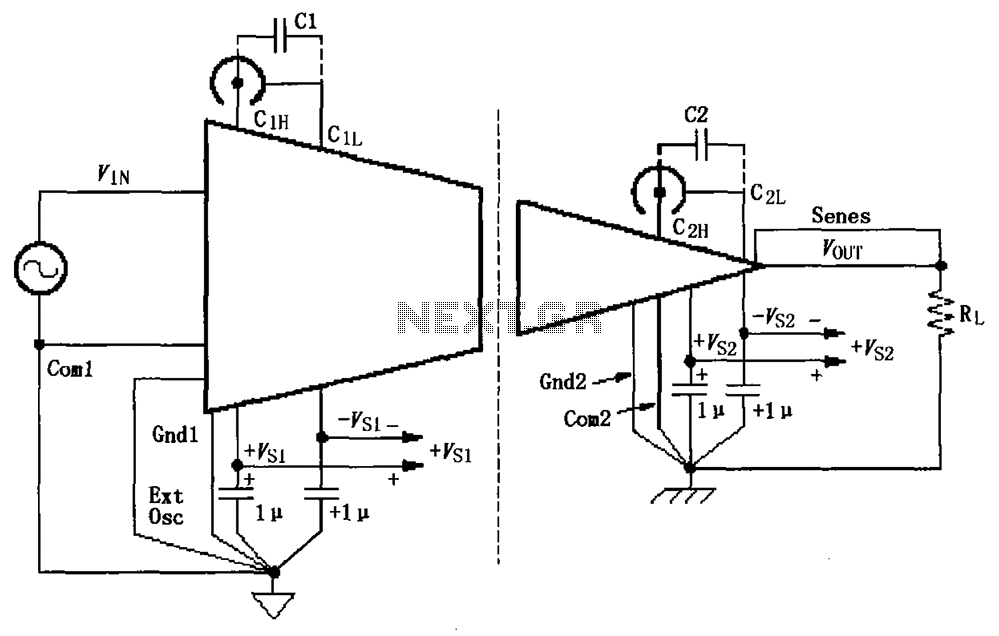
The basic connection circuit for ISO120/121 includes signals and power supply. Each power supply terminal must have a 1 µF tantalum capacitor as a bypass filter, and the printed circuit board layout should allow for the bypass capacitor to...
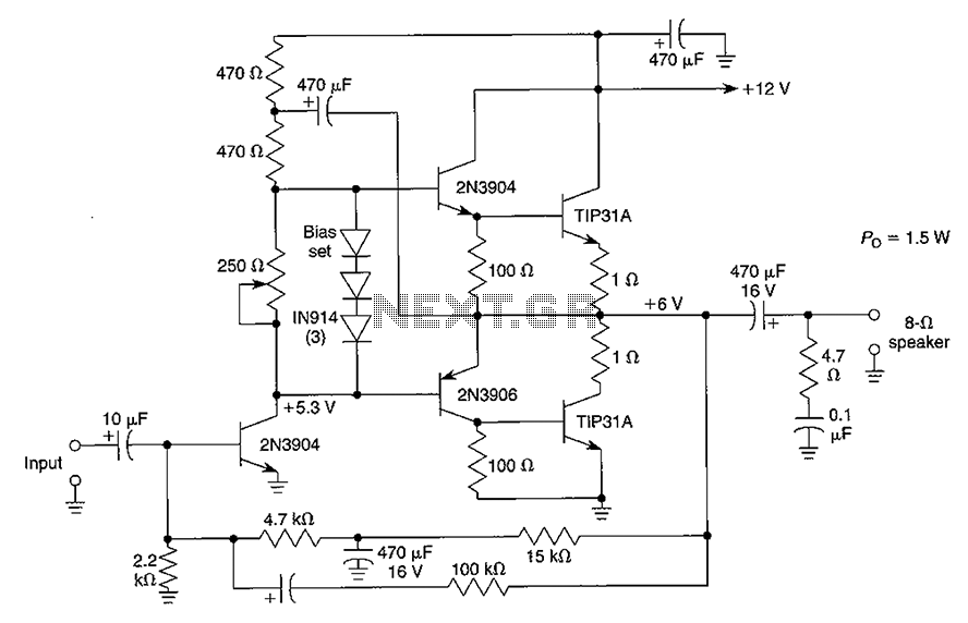
Although the integrated circuit (IC) has largely replaced this circuit, the flexibility of the discrete device design still makes it practical. The components are readily available and cannot easily be eliminated. If desired, a small piece of metal can...