
Glow Plug Driver for R/C Flightbox

try it you can easily assume that Q2 and possibly T1 will be defective. I included a small list with possible replacements for the major components. I tried a couple of them and seemed to work satisfactory. An email from Mo in England indicates a logarithmic potentiometer is used to better control the current. It certainly does not harm to try that and use whatever works for you. All resistors, except Rm, (metal-film recommended) 1/8 watt (1/4 watt for carbon) & no less than 5% tolerance, unless otherwise posted.
C1 = 100uF/16V Electrolytic R1 = 100 Ohm, 1/2 watt 1 red jack C2 = 10nF, ceramic R2 = 1K 1 black jack C3, C4 = 10nF, mica R3 = 1K 1 amp meter, 1 to 6-amp (dc) Q1 = TIP42C R4 = 4K7 1 knob for potentiometer Q2 = NTE123AP R5 = 750K 1 coolrib for Q1 D2 = 1N5401 Rm =. 2 ohm/10W D1, D3 = 1N4002 P1 = 100K D4 = 1N4148F Here is a suggestion for a complete Power Panel IC1 = LM555 A couple possible substitutes, use at your disgression, no guarantees: For Q1: TIP32C, TIP42, TIP42A (or B), NTE332, ECG332.
For Q2: 2N3904, BC547, (or A or B), BC550, European TUN. For D1, 3: NTE116, ECG116, try others. For D2: NTE5801, try others. For D4: NTE519, ECG519, other 1N4148x types worked also. For IC1: NE555, TLC555, MC1455, HC555, NTE955M, ECG955, etc. The NTE123A did not seem to work and is not quite the same as the `AP` type. The 2N2222(A) did not work in the prototype and shorted out the circuit. The ECG and NTE/ECG substitutes are made by Sylvania (Philips). I build two units and both working fine. An on/off switch is not required for the glowplug driver since it only draws current when a glowplug is attached. As a matter of fact, the circuit is only powered (via Q1) via a connected glowplug. Just in case you were wondering how the positive (+) side of the circuit is connected. The starter motor runs directly from the flight box battery, via the jacks on the power-panel, and has it`s own on/off switch.
Same scenario for the fuel pump, but includes a reverse switch to pump the fuel in or out the tank/cannister. For all components, substitutes are fine. D1 and D3 are regular 1N4002 diodes. You may substitute with the 1N4001, or 1N4003. D4 (1N4148F) is an ultra-fast switching silicon diode with a 100V prv. The regular and more familiar 1N4148 seems to work also. Q1 is a PNP power transistor/switch with a TO-220 case, 6A, 80/100V, 65 watts. Don`t be afraid to experiment, and don`t forget the coolrib on the TIP42, it may be needed. I strongly recommend a power supply if you`re gonna experiment and turn up the voltage slowly while watching the ampmeter.
My own experiments resulted in 3 burned out glowplugs, 2 TIPs, and 2 NTE123AP. Q2 is a NPN silicon, AF/RF Amp/Driver, transistor to drive Q1. If you substitute, stick with the `driver` type, other may burn-out the very second you apply power. Again, try using whatever you have in your parts-box first, but try to match the current/voltage parameters as close as you can and make sure it is able to drive Q1. Whatever transistor you use for Q1 or Q2, watch the orientation of the the emitter, base and collector and don`t assume it is the same as the original or as shown in the component layout.
The tab for the metal case transistors (Q2) is always the emitter. Remember, Q2, as mentioned before, should be a driver-type-transistor (or close to it) in order for it to supply enough current to Q1. In regards to the 750K value of R5, it is fine to combine different resistors to get to that value. I used two 1M5 resistors in parallel myself. Works fine! So does 680K+6M8 (754K). The CMOS timer, MC1455 🔗 External reference
Related Circuits
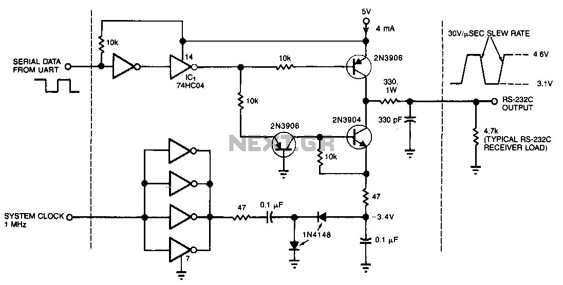
This circuit draws only 4 mA from a 5-V supply while driving a standard RS-232C receiver. The system clock drives a de-de converter that produces -3.4 V. The frequency can range from 0.5 to 8 MHz, but a range...
This is a status panel driver circuit. This circuit is used to turn on lamps or LEDs in a graphic panel that represent faults, actions, and the status of an application. The status panel driver circuit is designed to control...
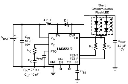
The LM3551 and LM3552 are fixed frequency, current mode step-up DC-DC converters featuring two integrated NFETs. These devices facilitate the design of a straightforward and highly precise LED brightness control system. They are capable of driving loads up to...
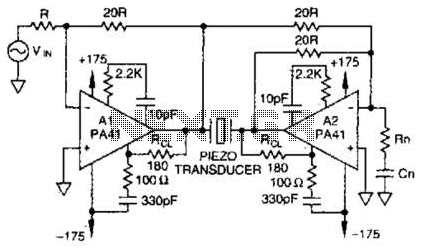
Using a PA41 from Apex Microtechnology, this monolithic amplifier is capable of 350-V operation and delivers 660 V peak-to-peak in a bridge circuit. The PA41 is a high-performance monolithic amplifier designed for applications requiring high voltage and high power output....
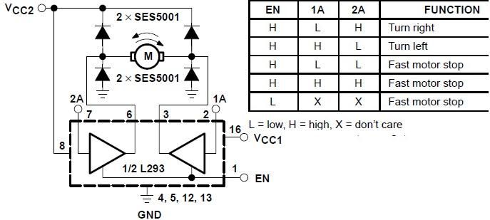
The L293 is designed to provide bidirectional drive currents of up to 1 A at voltages ranging from 4.5 V to 36 V. The L293D variant is capable of delivering bidirectional drive currents of up to 600 mA at...
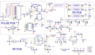
The Q-Switch driver for an old YAG laser failed. A replacement was over $1000, so a custom driver was built for less than $300 (see picture and schematic below). The specifications required were at least 20W into a 50-ohm...