
Bidirectional motor control using L293 driver

The L293 and L293D are integrated circuits commonly utilized in applications requiring motor control, particularly in robotics and automation systems. These devices facilitate the control of DC motors and stepper motors by allowing bidirectional operation, which is essential for applications where precise movement is required.
The internal structure of the L293 includes two H-bridge configurations, enabling control over the direction and speed of the motor. Each H-bridge consists of four switches that can be activated in different combinations to achieve the desired motor operation. The use of Darlington transistors in the output stage allows for high current gain and improved efficiency, making the L293 suitable for driving larger loads.
When implementing the L293 in a circuit, it is crucial to ensure proper voltage levels for VCC1 and VCC2. VCC1, the logic supply, powers the internal logic circuitry of the L293, while VCC2 provides the necessary power for the motor. It is advisable to use decoupling capacitors close to the power supply pins to filter out noise and ensure stable operation.
The enable pins (1, 2EN and 3, 4EN) play a critical role in determining the operation state of the drivers. By controlling these pins, users can effectively switch the motor on and off as needed, allowing for flexible control schemes. The high-impedance state of the outputs when disabled prevents any unwanted current flow, protecting both the drivers and the motor.
In summary, the L293 and L293D are versatile motor driver ICs that provide essential functionality for controlling motors in various applications. Their ability to handle bidirectional drive currents, coupled with the internal H-bridge configuration, makes them an ideal choice for projects requiring precise motor control.The L293 is designed to provide bidirectional drive currents of up to 1 A at voltages from 4. 5 V to 36 V. The L293D is designed to provide bidirectional drive currents of up to 600-mA at voltages from 4. 5 V to 36 V. Each output is a complete totem-pole drive circuit, with a Darlington transistor sink and a pseudo-Darlington source. Drivers are ena bled in pairs, with drivers 1 and 2 enabled by 1, 2EN and drivers 3 and 4 enabled by 3, 4EN. When an enable input is high, the associated drivers are enabled and their outputs are active and in phase with their inputs. When the enable input is low, those drivers are disabled and their outputs are off and in the high-impedance state.
With the proper data inputs, each pair of drivers forms a full-H (or bridge) reversible drive suitable for solenoid or motor applications. In this bidirectional stepper motor controller electronic project VCC1 is logic supply and must me between 4.
5 and 7 volts ( typically 5 volt) and VCC2 is the power supply for the motor and must be from VCC1 up to 36 volts 🔗 External reference
Related Circuits
It is entirely feasible and acceptable to control various outputs while sitting at a PC terminal. A simple hardware circuit and software are utilized to interface with a 7-segment rolling display. The printer port of a PC provides a...
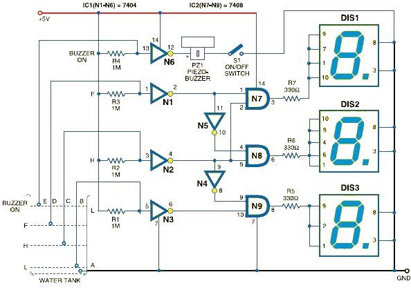
This schematic outlines a simple electronic circuit designed to indicate water levels using a 7-segment display. The circuit shows water levels by displaying 'L', 'H', and 'F' for low, half, and full levels, respectively. It is based on the...
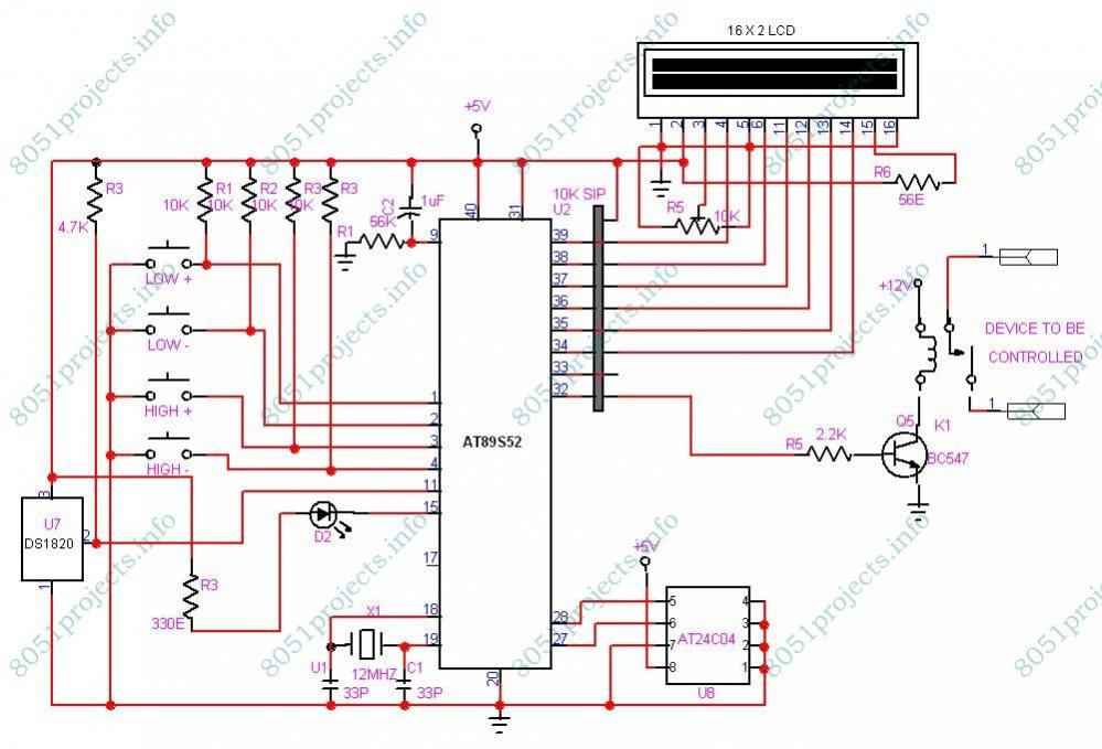
This project is designed to monitor and control temperature. The system utilizes the DS1820 temperature sensor to measure the temperature, which is then displayed on an LCD. It features two preset levels: a low preset and a high preset....
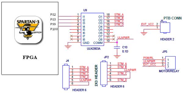
The Spartan-3 Primer board features external stepper motor interfacing, as illustrated in the accompanying figure. The stepper motor is driven by a ULN2803A, which is a high-voltage, high-current Darlington transistor array. The ULN2803 is utilized as a driver for...
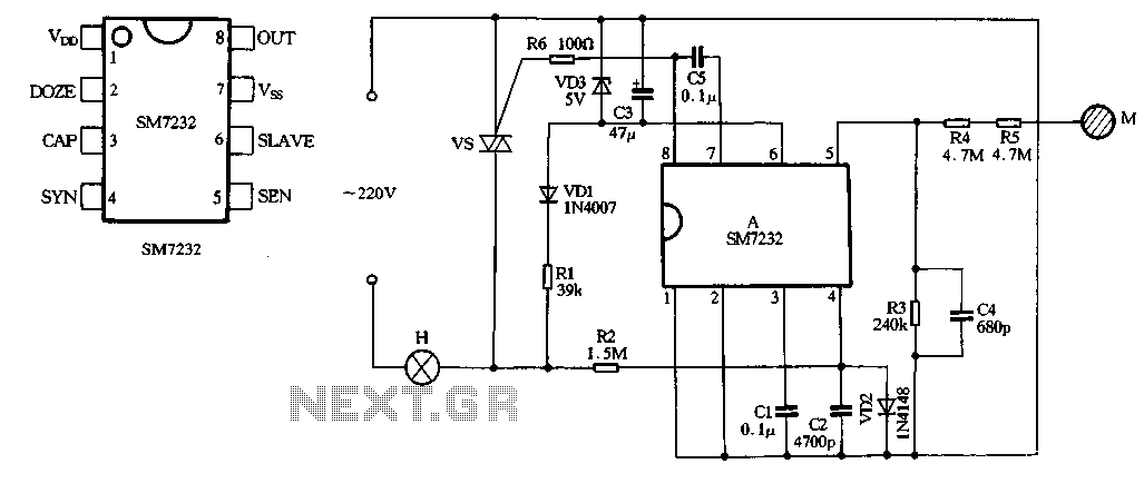
The core component of the circuit is the dimmer, utilizing the SM7232 integrated circuit. The pin configuration includes: 1) VDD, the positive power supply terminal; 2) DOZE; 3) CAP; 4) SYN, which synchronizes input power frequency using an internal...
This application note outlines the transmission of I²S audio data streams between two audio components using a single shielded twisted-pair (STP) wire, employing the MAX9205 10-bit LVDS serializer and the MAX9206 10-bit LVDS deserializer. Low-voltage differential signaling (LVDS) serves...