
Gray Projects
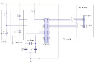
To enhance the functionality of the printing system, a detailed circuit design is necessary, focusing on the integration of the FT232RL USB chip for communication with the microcontroller. The microcontroller should be programmed to manage motor control, including acceleration and deceleration profiles tailored to the weight of the assembly. A feedback loop can be established using the two-channel encoder to provide real-time position data of the paper roller, allowing for precise control of the paper feed mechanism.
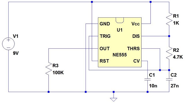
The circuit should include a power management system to ensure that the microcontroller and motor receive adequate power without exceeding the limits of the +5V source. This can be achieved through the use of voltage regulators and current limiting resistors to prevent overloading the power supply. Additionally, capacitors can be employed to smooth out voltage fluctuations, ensuring stable operation.
For the motor control, an H-bridge driver circuit can be implemented to allow for bidirectional control of the stepper motor, enabling both forward and reverse movements. The H-bridge should be capable of handling the current requirements of the motor to prevent overheating and ensure reliable operation.
Incorporating a PID (Proportional, Integral, Derivative) controller into the microcontroller's programming can help optimize the motor's response to changes in load and improve overall print quality by minimizing vibrations during operation. The PID controller can adjust the motor speed based on feedback from the encoder, allowing for dynamic adjustments as the printer operates.
Finally, thorough testing and calibration of the entire system will be essential to ensure that all components work harmoniously. This includes fine-tuning the timing of the paper sensor activation based on the roller's movement and ensuring that the print head maintains an appropriate distance from the paper to prevent distortion during printing.Then I learned to drive it. Turns out my greatest enemy is inertia. What I`ve built is just so damn heavy and massive I can`t just start off the motor at full speed. Being a half-assed physicist I should know that already. But I guess experience is also needed. So to get the motor running properly - careful speedup, slowdown and backslash delay at return need to be coded. Actually. I`m making this all up as I go, don`t have any formal education and doing inertia calculations seems like a pain. So I try and see what works. But basically I need to reduce weight. All that steel and heavy aluminium beams I`m moving along take a lot of effort. And cause excessive shaking of the whole machine resulting in some jitter at the printed page. Also the HP printer carriage is designed to slant forwards and backwards at different stages of the rail.
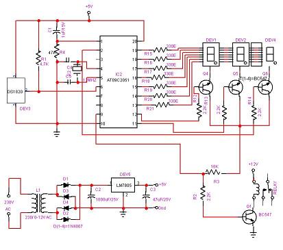
The movement of the whole assembly though causes it to shake at the wrong places, more distorting the printed page. I added my old USB chip (FT 232RL) to the game so that I can both control and get diagnostics from the microcontroller.
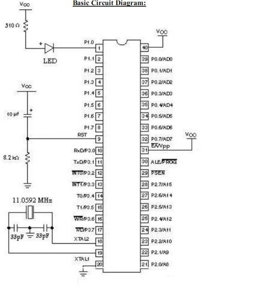
The MCU runs at 20MHz now and I think it wouldn`t keep up with the printer at any slower frequency. Getting diagnostics allowed me to plot the main roller/motor movement sequence: I had a lot of trouble figuring out when to turn the paper sensor on. To understand what the printer does I had to rebuild the old printer from the pieces I had. And I discovered that there`s a lever that is pushed when the printer head moves to the very right. When this lever is pushed - no paper is fetched if the roller turns. And paper fetching is actually done with roller turning backwards. But adding another sensor is a pain so I just deduced from the roller movement when it expects the paper sensor to turn on.
This happens when the roller moves backwards, then sits still for 450-600ms, and then moves again backwards. A few cm after that I will turn the paper sensor on and printing commences. The paper-on period is between the two vertical tics on the image. Another thing I discovered is that the printer is, well, too fast for my rig. It scrolls paper through at mindnumbing 12cm/second. While my rig can probably do 2-3cm/second. However I can control this by printing my stuff inside a box/frame. That forces the printer to slow down. But even that is not enough, the edges get distorted due to slow movement. I need a stronger stepper motor. It is a bit fuzzy but it`s mostly down to the printer head being too much distance away from the paper surface, paper being slanted and also the print head itself is slanted.
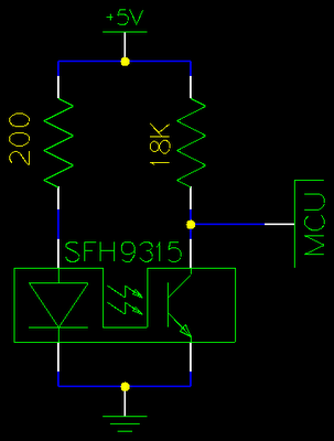
So lots of fiddling to do to get to better quality. I can report some progress. The paper jam errors I got before are over. Printer now properly initializes, cleans itself and goes into idle mode. The problem was with my motor response timing and the way I had coded it. Fixed now. I also modularized my designs so everything goes through the energy chain now. Printing still does not work though. When I try to print I eventually get a paper/cartridge jamming error. But what I`ve got now is I think a purely software problem. Will have to try new things again to resolve this. So after the hassle I decided to reverse engineer the optical paper roller position sensor so that I can fake it digitally. I attached a set of wires to it to see what was happening: After running oscilloscope I determine what each wire did.
Only two of them had a changing signal when the wheel turned - we`ve got a 2 channel encoder. This is what the wires represent: Now with wires there I could start generating a circuit. I spent a better part of the night trying to make it work. It tended to just crash the printer. Finally I realized it was an electrical problem - I was drawing way too much current from the +5V source - apparently there`s a really weak current pump behind it. So can I print stuff now Not really. The printer has some really fanc 🔗 External reference
Related Circuits
Best Microcontroller Projects. Do you want to learn how to use a microcontroller in your electronic projects, or do you need inspiration for your next project? If so, you have found the right place! Here is a tutorial on...
The voltage regulator circuit was constructed using the LM317T, a three-terminal regulator. A heatsink was utilized to cool the LM317T. The output voltage can be set anywhere in the range of 1.5 volts to 30 volts; however, for this...
Microcontrollers and Microprocessors - The 8051 Projects Page! Discover comprehensive information on 8051 projects here. Everything you wanted to know about 8051 projects is available. The 8051 microcontroller, developed by Intel in the 1980s, is a widely used microcontroller in...
The issue began when a girlfriend expressed her frustration with mosquitoes disrupting her nights. It was recognized that mosquito sprays provide only temporary relief, as the insects tend to return after some time. A suggestion was made for an...
The dual-channel thermometer is a simple project based on a PIC microcontroller with ADC capabilities. It is an inexpensive thermometer that utilizes low-cost components and does not require high-sensitivity or expensive sensors. Instead, it employs a simple silicon diode...
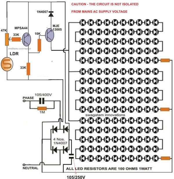
At times, it is quite frustrating to see street lights remaining switched on even during broad daylight. The current circuit for an automatic night light can effectively address this issue. This article explains how to construct such a system....