
Guitar Amplifier

The Combo amplifier design features a classic architecture that integrates both preamplification and power amplification stages within a single unit, making it versatile for various audio applications. The two-FET preamplifier stage is designed to provide a high input impedance, allowing it to interface effectively with different musical instruments or microphones without significant signal loss. The inclusion of two inputs with different sensitivity settings enables users to connect instruments with varying output levels, enhancing the amplifier's usability.
The treble-cut control is an essential feature that allows for tonal shaping, enabling users to modify the high-frequency response to suit their preferences or the acoustic characteristics of the instrument being amplified. The optional switch for overdrive or treble enhancement introduces additional versatility, allowing the user to achieve a range of sounds from clean tones to more aggressive, distorted sounds typical in rock music.
The design's attention to thermal management is critical, particularly when utilizing Darlington transistors, which can generate significant heat during operation. The choice of a TO-126 case transistor ensures that the sensing transistor (Q4) is thermally coupled to the output transistors, allowing for accurate temperature monitoring and preventing thermal runaway conditions.
In terms of operational setup, the initial configuration of setting the volume control and Trimmer R9 to their minimum values is crucial for ensuring a safe power-on sequence. This precaution helps to avoid sudden loud outputs that could damage speakers or lead to an unpleasant user experience. After powering the circuit, adjusting R9 to achieve a current draw of 25 to 30 mA ensures that the amplifier operates within its designed parameters, promoting longevity and reliable performance. Overall, this Combo amplifier design encapsulates the essence of vintage amplification while incorporating modern design considerations for thermal management and user flexibility.The aim of this design is to reproduce a Combo amplifier of the type very common in the `sixties and the `seventies of the past century. It is well suited as a guitar amplifier but it will do a good job with any kind of electronic musical instrument or microphone.
5W power output was a common feature of these widespread devices due to the general adoption of a class A single-tube output stage (see the Vox AC-4 model). It also features a two-FET preamplifier, two inputs with different sensitivity, a treble-cut control and an optional switch allowing overdrive or powerful treble-enhancement. * In all cases where Darlington transistors are used as the output devices it is essential that the sensing transistor (Q4) should be in as close thermal contact with the output transistors as possible.
Therefore a TO126-case transistor type was chosen for easy bolting on the heatsink, very close to the output pair. * Set the volume control to the minimum and Trimmer R9 to its minimum resistance. * Power-on the circuit and adjust R9 to read a current drawing of about 25 to 30mA. 🔗 External reference
Related Circuits
This simple power MOSFET audio amplifier circuit utilizes a TL071C operational amplifier and two MOSFETs (IRF9530 and IRF530), capable of delivering up to 45 Watts to an 8-ohm speaker. The schematic is based on a Siliconix application and incorporates...
This circuit turns off an amplifier or any other device when it remains idle for 15 minutes. It is powered by the amplifier's tape output. The described circuit functions as an automatic power management system, designed to enhance energy efficiency...
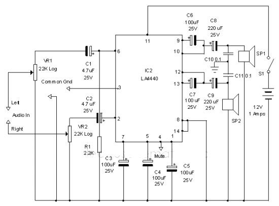
The LA4440 audio amplifier IC can be utilized to design a straightforward stereo power audio amplifier project, capable of delivering 6 watts of output power into an 8-ohm load. This audio amplifier IC features a minimal number of external...
The PhoneAxe is a unique design that incorporates a passive filter network within a 1/4" phone plug/coaxial cable. It is specifically engineered to facilitate the matching of electric guitars to the magnetic phono input found on standard hi-fi amplifiers....
The minimum voltage required for this circuit is 8 volts, while the maximum voltage is 28 volts. It can be used to amplify audio signals in electronic devices such as radios, DVDs, MP4 players, and MP5 players. The circuit...
The intermodal servo preamplifier circuit operates at 115V and 60Hz, designed to provide a differential output for a servo motor amplifier. It features an inverting connection using an operational amplifier (op-amp), along with an additional op-amp configured to create...