
Guitar Patch Cord

Most hi-fi audio amplifiers offer two primary types of signal inputs: line-level auxiliary inputs, which typically require a minimum signal level of 200 mV for optimal output power and have a nominal frequency response from 20 Hz to 20 kHz with an input impedance of less than or equal to 30 kΩ. This input configuration does not align well with the output of guitar pickups. A common approach to achieve proper guitar-to-line input matching involves employing a flat-response dual op-amp circuit that provides impedance buffering and sufficient gain, usually around 10 dB. This type of input stage is prevalent in many solid-state guitar amplifiers.
The second type of input available on hi-fi amplifiers is the classic magnetic phono input. This input type provides a simpler solution for interfacing guitars with hi-fi amplifiers due to its inherent gain characteristics. A compensating equalization network can be inserted between the guitar and phono input to achieve a flat overall response. The RIAA playback equalization acts as a multiple low-pass filter network; therefore, a high-pass network with adequate nominal attenuation at a reference frequency (for example, -24 dB attenuation at 1 kHz for a 50 mV to 3 mV signal) can be used.
The equivalent circuit of the guitar pickup is represented on the schematic, where Vp denotes the electromotive force induced in the guitar coil, Lp represents the coil inductance (approximately 4 Henries for a Gibson Les Paul humbucking pickup), and Rp indicates the coil's series resistance, typically around 7 kΩ. These parameters may vary based on the specific pickup design, as factors such as winding techniques, magnet/coil geometry, and adhesive materials all influence the sound characteristics of the electric guitar pickup.
The simplified equivalent circuit for the pickup includes a shunt capacitance (Cj) of 200 pF, which is typical for a standard 6-foot musical instrument coaxial cable. The PhoneAxe filter network consists of just two components: a series capacitor (C) and a shunt resistor (R). Typical values for these components that yield satisfactory results with a Gibson Les Paul humbucker pickup are C = 330 pF and R = 100 kΩ. The filter response at the phono input, represented by a 47 kΩ load (the standard input impedance for magnetic phono inputs), can be visualized using a Java design applet. The overall amplifier response is derived by convolving the filter response with the RIAA playback response and the user's bass and treble settings. The user has the ability to adjust the values of R and C within the PhoneAxe network, as well as the cable shunt capacitance (Cj), the series resistance of the pickup (Rp), the amplifier's input resistance (Ramp), and the inductance of the pickup coil (Lp). These modifications are reflected in the graphical output, which highlights the characteristic 20 dB/decade low-frequency roll-off and displays the frequency of the LC peaking feature.The PhoneAxe is an original design by the author of a passive filter network built into a 1/4" phone plug/coaxial cable, and is designed to allow electric-guitar matching to the magnetic-phonograph input on common hi-fi amplifiers. Most guitar amplifiers have "high input impedance" typically greater than 200 kohms. The reason for this is that the typical electric guitar pickup is a inductive magnetic transducer with frequency-dependent impedance. At high frequency, the mutually induced pickup voltage is dropped across the pickup-coil self-inductance (back EMF) if the pickup load impedance (i.
e. amplifier input) is too low. Therefore, a high impedance amplifier input is required to prevent high frequency "loading" effects which are audible as a high-frequency attenuated "dull" sound. Most hi-fi audio amplifiers have two types of signal inputs: the line-level auxiliary inputs (for tuner, tape, CD etc.
) typically require 200 mV or more signal-level for efficient output power, have a nominal flat frequency response from 20 Hz to 20 kHz and an input impedance <= 30 kohms. This input by itself is not well matched to the guitar pickup output because of : The typical active solution for guitar/line-in matching is a flat- response dual op-amp circuit which provides impedance buffering and sufficient gain (typically 10 dB) for driving the line-level input.
This is generically the type of input stage used in most solid-state guitar amplifiers. A simplified schematic diagram is shown below: The second type of hi-fi amplifier input is the classic magnetic-phono input. A simpler solution for guitar to hi-fi amplifier interfacing can be realized using this phono input. The phono input is characterized by : Since there is abundant gain at the phono-input, a simple compensating equalization network can be inserted between the guitar and phono-input to realize effectively an overall flat response.
Since the RIAA playback equalization is really a multiple low pass filter network, we insert a high pass network with sufficient nominal attenuation at some reference frequency (e. g. 50 mV -> 3 mV or -24 dB attenuation at 1 kHz). The schematic diagram below shows typical component values. The boxed section at the left represents the equivalent circuit of the guitar pickup with Vp the EMF induced in the guitar coil, Lp the coil inductance (4 Henries being a typical value for a Gibson Les Paul hum-bucking pickup) and Rp the coil series resistance, typically 7 kohms.
These values will vary with pickup design. Indeed, the exact details of how the pickup coil is wound, the geometry of the magnet/coil layout, the adhesive used to fix the coil in place all play a role in shaping the sound characteristics of the electric-guitar pickup. The equivalent circuit for the pickup presented here is very simplified: The guitar cable shunt capacitance Cj is 200 pF for standard musical-instrument coaxial cable of 6 foot length.
The PhoneAxe filter network described here consists of just two components: a series capacitor C and a shunt resistor R. Typical values for these components which produce good results in practise (for a Gibson Les Paul hum-bucker pickup) C = 330 pF and R = 100 kohms.
The Java design applet below shows the filter response at the phono-input (represented by a 47 kohm load, the typical input impedance of magnetic-phono inputs). The net amplifier response (not shown here) is obtained by convolving the filter response with the RIAA playback response, and the users BASS and TREBLE response settings.
The user can modify the R and C values of the PhoneAxe network as well as the cable shunt capacitance Cj, the series resistance of the pickup Rp, the input resistance of the amplifier Ramp and the inductance of the pickup coil Lp. The changes are updated in the graph. Note the characteristic 20 dB/decade low frequency rolloff. The frequency of the LC peaking feature is also displayed: The fi 🔗 External reference
Related Circuits
A 4x10" Ashdown ABM bass cabinet is powered by a Hughes & Kettner bass amplifier head. There is an intention to modify the amplifier head to enhance its functionality. The Ashdown ABM bass cabinet features four 10-inch speakers, which are...
Frequency changes produced in a Colpitts oscillator by a metal object near the tank coil are indicated by a 565 PLL connected as a frequency meter. The oscillator frequency increases when the search coil is brought near a non-ferrous...
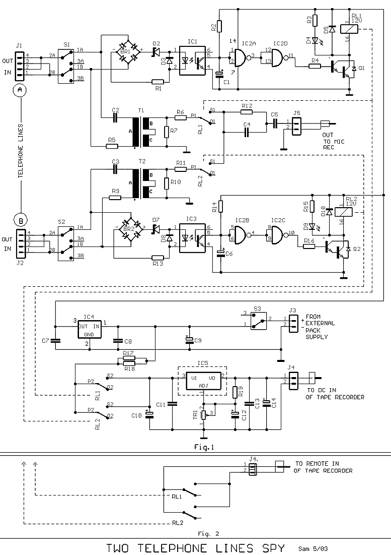
Many times exists the need recording some conversations from a telephone line and this it's relatively easy. If we want however to have the possibility recording from two telephone lines simultaneously in a tape recorder, we needed a circuit...

This design utilizes a well-established circuit topology for the power amplifier, employing a single-rail supply of approximately 60V and capacitor coupling for the speaker(s). The benefits for a guitar amplifier include simple circuitry, even with relatively high power outputs,...
This circuit is a phaser circuit, as used in guitar foot-pedal effects. It used 11 sections of op-amp such as LM324 but others will do. The whole circuit works of a dual rail supply: +/- 9v. The 0v rail...

Basic features include an internal 512k-bit EEPROM, allowing for continuous recording and playback at any time, with long-term retention of voice data after power loss. The voice recording time is 20 seconds, and it supports segmented recording and playback....