
Guitar Control

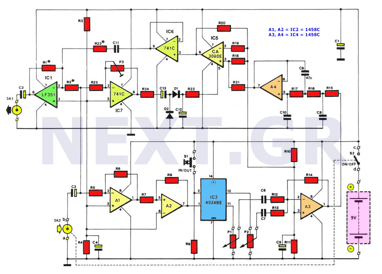
The circuit utilizes IC1A as the primary amplification stage, which is essential for processing audio signals. In the inverting amplifier configuration, the gain is defined by the formula -R_f/R_in, where R_f is the feedback resistor and R_in is the input resistor. The three-way switch allows for versatile gain settings by connecting various resistors in parallel with R4, thus providing flexibility in adjusting the amplification level based on the application requirements.
Following the inverting amplifier stage, the signal is processed by an active three-band tone control circuit built around IC1B. This stage is designed to adjust the bass, midrange, and treble frequencies of the audio signal, allowing for enhanced sound customization. The tone control circuit typically employs capacitors and resistors configured in such a way as to create band-pass filters for each frequency range. When the tone controls are set to their center position, the circuit is designed to achieve a unity gain, ensuring that the audio signal passes through without any amplification or attenuation.
Overall, this schematic effectively combines an inverting amplifier with a sophisticated tone control stage, making it suitable for various audio applications where signal manipulation and quality are paramount. The careful selection of component values and configurations allows for a high degree of control over the audio output, catering to diverse listening preferences.IC1A op-amp is wired as an inverting amplifier, having its gain set by a three ways switch inserting different value resistors in parallel to R4. This input stage is followed by an active three-band tone control stage having unity gain when controls are set in their center position and built around IC1B.
🔗 External reference
Related Circuits
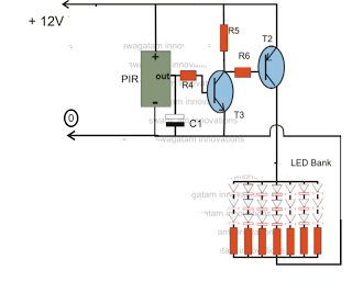
The circuit is an LED driver that responds to ambient light as well as the presence of an intruder, varying its illumination accordingly. Additionally, it includes an ambient light sensor to turn the LEDs on and off, and a...
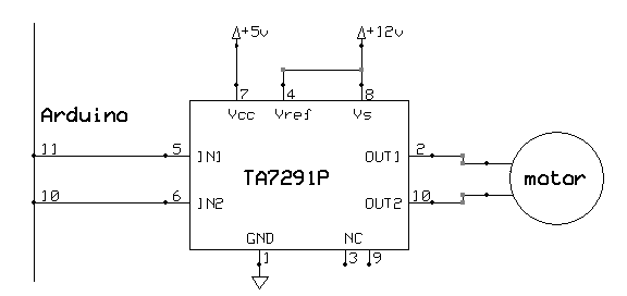
Buffer ICs (7417, 7414) were utilized to isolate the signals to and from the Arduino. This setup protected the board and provided power for external devices without drawing it from the Arduino. An H-bridge serves a similar purpose as...
The sub-harmonic bass generator is a sound-producing unit designed for guitars, capable of generating sounds similar to those of a bass guitar. This device employs an octave generator that operates differently from traditional sound coloring methods such as filtering...

The LTC3722-1 and LTC3722-2 phase-shift PWM controllers offer all necessary control and protection functions for implementing a high-efficiency, zero voltage switched (ZVS), full bridge power converter. The adaptive ZVS circuitry delays the turn-on signals for each MOSFET, independent of...
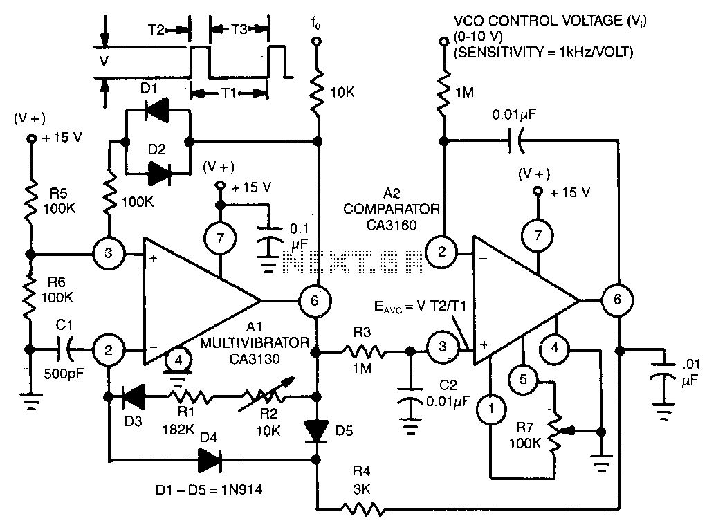
This circuit utilizes a CA3130 BiMOS operational amplifier as a multivibrator and a CA3160 BiMOS operational amplifier as a comparator. The oscillator exhibits a sensitivity of 1 kHz/V, with a tracking error of approximately 0.02% and a temperature coefficient...
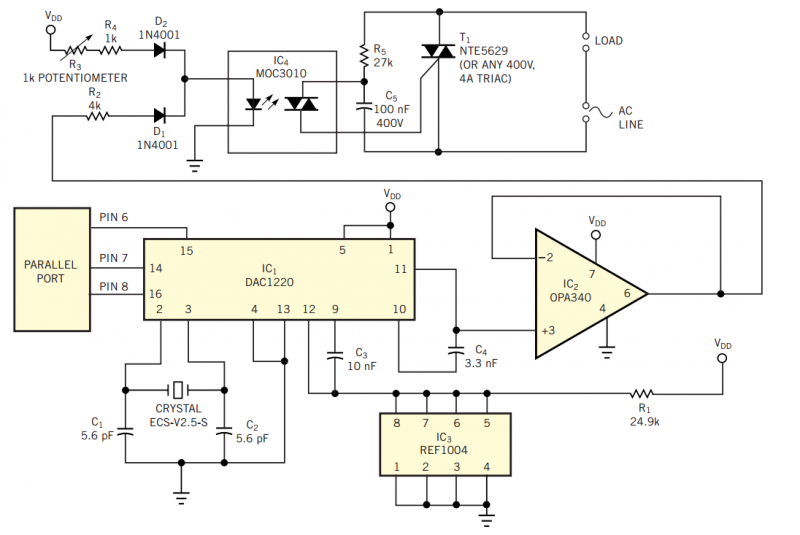
Using the simple circuit in Figure 1, you can control the light intensity in your room or work area from your PC. The heart of the circuit is a low-power D/A converter that converts digital words from a computer's...