
DC Motor Control

The circuit design incorporates buffer ICs to ensure signal integrity and protect the Arduino from potential overloads when interfacing with external devices. The TA7291P H-bridge is employed to facilitate motor control, allowing for both speed modulation and directional changes through the manipulation of PWM signals. The half-bridge design of the TA7291P simplifies the control of motor terminals, providing the ability to switch between high and low states effectively, which is essential for controlling the motor's operational characteristics.
The integration of a potentiometer into the system allows for intuitive user control, translating the physical position of the potentiometer into corresponding motor behavior. This setup mimics the functionality of a throttle, providing a dynamic response to user input. The use of the Arduino's map function enables precise scaling of the potentiometer's output to the desired motor speed and direction, enhancing the overall control and responsiveness of the system.
In summary, the combination of buffer ICs and the TA7291P H-bridge, along with the potentiometer interface, constitutes a robust and versatile solution for DC motor control, suitable for various applications requiring precise speed and direction management. The design emphasizes the importance of signal isolation and power management while maximizing the performance and reliability of the motor control system.We used buffer IC`s (7417, 7414) to isolate the signals to and from the Arduino. This protected the board, and provided power for external devices without drawing it from the Arduino. An H-bridge can be thought of in much the same way. It is the interface between an electrical signal and an electrical power source. Though they share thesame medium, their functions are vastly different. The H-bridge is a common circuit used to control the speed and direction of a DC motor with low current PWM signals. The H-bridge you will be using is the TA7291P ( datasheet ). It is a pair of half bridges that can source 1 Amp. DC motors are turned on by applying a voltage across the two terminals. The rotation speed can be controlled by increasing or decreasing the applied voltage. Changing the polarity of the applied voltage changes the motor`s direction of rotation. We can use half bridges to control both the speed and direction of rotation of a DC motor. Half bridges are essentially high power digital buffers; the output goes to 0V when the input is low, and the output goes to Vs when the input is high.
To power a motor, we can use half bridges to drive one terminal high and the other low. We also can control the voltage applied to the motor by sending one half bridge a PWM signal. For example, if we hold one bridge low and drive the other bridge high 50% of the time, (for Vs=+12) the motor will behave as if we applied 6VDC. Notice that we can apply zero volts to the motor by either driving both bridges low or both high. Some h-bridges are designed so that one of these modes puts the outputs in a "coast to stop" mode (L-L for the TA7291P); the other mode causes a stronger "brake" stop.
In this lab, you will be using only the digital output buffer and the voltage follower. As breadboard space is limited, these are the following schematics you should implement. Before you continue to the software tasks, make sure that your DC motor is working by supplying 5V from the benchtop power supply. The Arduino will not be able to supply enough current. Plugging the DC motor into the 5V and GND will trigger a board shutdown in order to prevent further damage.
Control the direction and speed of the provided DC motor with a potentiometer. The motor should behave like the throttle of a boat. A potentiometer twisted all the way to the right should have the motor spinning fast in one direction. As the potentiometer is twisted left, the motor should slow down and then begin spinning the other direction.
Tie the direction and speed of the motor spinning to the direction and speed of the potentiometer rotation. The faster you spin the potentiometer, the faster the motor should spin. The map function provided by the Arduino libraries provides an easy way to scale a number within a range.
It is called by map (value, fromLow, from High, toLow, toHigh). fromLow and fromHigh are the initial range of value. toLow and toHigh are the new range of values. The function returns the scaled value. Velocity can be approximated as a change in position over a change in time. You can keep track of time in the Arduino with the millis()function. millis() returns the millisecond value of the onboard clock. It takes about 5 days for this counter to run-over and restart. Some H-bridges, such as the LMD18200, simply have inputs for direction and speed (PWM). The most intuitive way of using them is to provide two input signals for direction and PWM. (The LMD18200 is rated for 55V, 3 Amps, and can be checked out from the department. ) Simple PWM consists of a single, variable duty-cycle signal in which both direction and amplitude information is encoded. A 50% duty-cycle PWM signal represents zero drive, since the net value of voltage (integrated over one period) delivered to the load is zero.
A 25% duty-cycle PWM signal represents current flow from OUT2 to OUT1 whereas a 75% duty-cycle represents current flow 🔗 External reference
Related Circuits

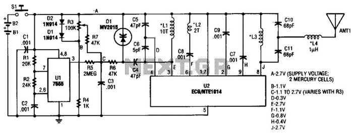
A voltage-controlled oscillator using the NE555. This circuit is commonly referred to as a voltage-to-frequency converter because the output frequency is altered by varying the input voltage. As previously noted, pin 5 serves as the voltage control terminal, which...
Many audio systems consist of separate units, where typically only the amplifier is equipped with a remote control receiver module for economic reasons. Control signals are then transmitted to other units using patch cables. For instance, the tuner and...
This information pertains to a dosing pump control circuit that utilizes the LM317 integrated circuit (IC). The circuit operates with a power supply of 24V DC and is capable of adjusting the output voltage to 1.25V. The LM317 is a...
The HC-06 module is a slave mode serial Bluetooth data link manufactured by CSR. In this project, a mobile phone communicates with the AT89C2051 microcontroller via the HC-06 module. The complexity of the communication has been encapsulated within a...
This transmitter can be utilized for multiple applications. An INS8048L microprocessor produces various codes based on keypad inputs. These codes are modulated onto a 40-kHz carrier frequency. Additionally, Q1 drives infrared LEDs LED1 and LED2. The transmitter circuit primarily consists...
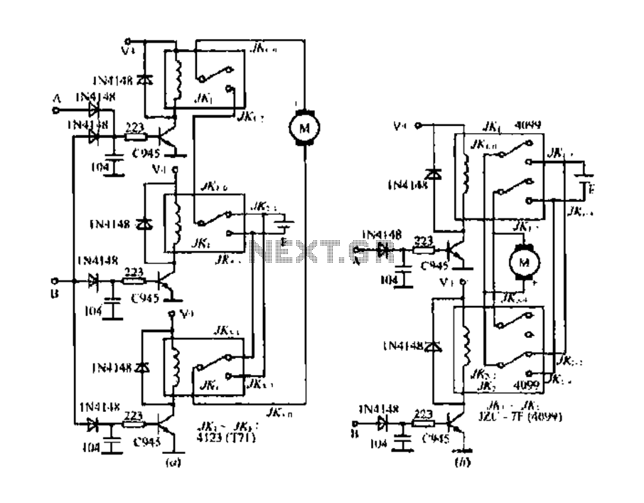
The DC motor E inversion control circuit utilizes a loop configuration with various relay contacts. It employs a single set of normally open/normally closed relay contacts. When both inputs A and B are low, relay KI is activated. In...