
H-Bridge Transistor Smoking (Bipolar BJT Transistor)
The circuit utilizes TIP 142 and TIP 147 transistors, which are NPN power transistors capable of handling significant current and voltage levels. The 1kΩ resistors serve as current-limiting components for the base of each transistor, controlling their switching states based on the input signals. The 1N5817 diodes are Schottky diodes, known for their low forward voltage drop and fast switching speeds, which help protect the circuit from back EMF generated by the motor during operation.
In the described operation, when R1 and R2 are set to 0V, and R3 is at 5V, the TIP transistors are activated, allowing current to flow from the 12V power supply through the motor, which operates within the expected voltage range of 8-10V. This indicates proper functionality under these conditions.
However, the issue arises when R4 is manipulated. The abnormal voltage drop to 1-2V across the motor suggests that the circuit is not providing sufficient current to maintain normal operation. This condition may be due to incorrect biasing of the transistors or an unintended path for the current that limits the voltage across the motor. The overheating and smoking of the transistor at R3 indicate that it is likely being driven into saturation or is experiencing thermal runaway due to excessive current flow, potentially caused by a short circuit or misconfiguration in the circuit.
To resolve this issue, it is advisable to check the connections and ensure that the resistors are correctly positioned and functioning. Additionally, verifying the integrity of the transistors and diodes is essential to prevent damage and ensure reliable operation. Proper heat sinking may also be necessary for the transistors to handle the thermal load without failure.Using the following circuit, with 12V appplied to the motor, and either high (5V) or low (0V) to each transistor through a 1k resistor. The transistors used are TIP 142 and TIP 147. The diodes I am using are 1N5817. When I apply 0V to R2, R1, and 5V to R3, the motor runs fine; voltage across it is 8-10V. However, whenever I connect 5V OR 0V to R4, the voltage across the motor is 1-2V, and the transistor at R3, starts getting really hot and smoking. 🔗 External reference
Related Circuits
The Metal-Oxide-Semiconductor Field-Effect Transistor (MOSFET) is analogous to the Junction Field-Effect Transistor (JFET) in several aspects. Both types are voltage-driven unipolar devices that rely on either electron or hole movement, but not both, unlike bipolar transistors. A key structural...

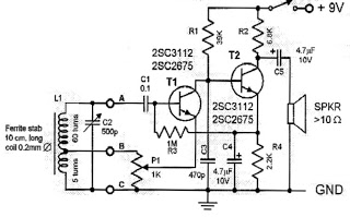
This design features a simple yet effective receiver with good sensitivity and selectivity. The circuit utilizes a compact three-transistor regenerative receiver with fixed feedback, primarily based on the BC549 transistor. The tuned circuit is intended for medium wave frequencies...
This circuit is a simple one-transistor Audion type radio powered by a 1.5 V battery. It utilizes a pair of standard low-impedance headphones, wired in series to achieve a total impedance of 64 ohms. The power supply to the...
The three circuits described provide a constant current to the LED (or LEDs) when the supply voltage reaches 15V or higher. The second and third circuits can be activated or deactivated through the input line by turning on the...
A very popular circuit for driving DC motors (ordinary or gearhead) is called an H-bridge. It's called that because it looks like the capital letter 'H' on classic schematics. The great ability of an H-bridge circuit is that the...
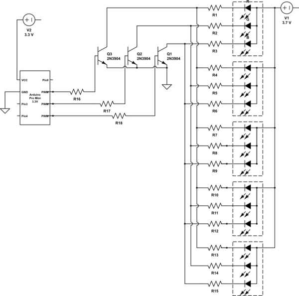
It is noted that the LEDs are not configured in parallel with the transistor. If they were, the LEDs would illuminate when the transistor is off. Instead, the LEDs are connected in parallel before entering the transistor. The transistor...
Warning: include(partials/cookie-banner.php): Failed to open stream: Permission denied in /var/www/html/nextgr/view-circuit.php on line 713
Warning: include(): Failed opening 'partials/cookie-banner.php' for inclusion (include_path='.:/usr/share/php') in /var/www/html/nextgr/view-circuit.php on line 713