
H-Bridge Tutorial

Pulse Width Modulation (PWM) is a technique for digitally controlling an output with a variable equivalent voltage. By averaging the signal over time, it effectively simulates a varying analog level while remaining digital in the short term. This method is efficient, as transistors operate most effectively when fully on or off rather than in a partially conducting state. Many modern microcontrollers, including Arduino and its derivatives, have built-in PWM generation capabilities. To control a standard H-bridge, four signals are required for the four transistors; however, using PWM necessitates two PWM signals and two standard digital signals. While it is theoretically possible to control the H-bridge with only two PWM outputs, caution must be exercised regarding the signal polarity relative to the transistors being driven. Some microcontrollers come equipped with a full bridge driver (such as Microchip's Enhanced Capture/Compare/PWM, or ECCP, in their 8-bit PIC chips), which can drive four outputs connected to the H-bridge, though it still requires four control lines. If both PNP and NPN transistors can be driven from the same logic line (i.e., when the motor power and logic rails are identical), the PWM can be connected to both A and B inputs, with direction control applied to C and D. In this configuration, it is necessary to invert the duty cycle when operating in reverse since the low portion of the duty cycle activates the motor, as indicated by "Inverted PWM."
To simplify control of the H-bridge, an overall enable line can be introduced, allowing for a single PWM-controlled enable line instead of a complex H-bridge driver. One approach involves adding an additional transistor that connects the bottom rail of the H-bridge to the negative supply. Pulsing this transistor will cause the motor to run only while the control signal is high, enabling overall speed control through PWM without concern for motor direction. However, the additional transistor may incur significant costs when using high-power transistors or MOSFETs, and depending on voltage rails, it could introduce a voltage drop of approximately 0.4 to 0.7V across each device. An alternative method is to use logic to filter the control lines, combining the PWM signal with the direction signals. In many scenarios, particularly with smaller toy motors, constructing a complete H-bridge circuit from scratch may be unnecessary. Utilizing an integrated chip can alleviate issues with offset voltages; if there is a discrepancy between the motor supply voltage and the logic voltage, drivers will be needed to interface between the logic and power transistors. Several recommended chips are available, with selection dependent on the power requirements of the motors involved.The H-bridge is a circuit used in electronic control of high current devices, particularly where the device polarity may be reversed, e. g. DC motors. The name comes from the fact that the circuit typically looks like a letter "H". The circuit shown has four switches and a motor. To apply a voltage across the motor a pair of diagonally opposite swi tches need to be turned on. Depending on which pair of switches are turned on the motor will turn one way or another. If both the top or both the bottom switches are turned on the motor will have no voltage difference across it so it won`t move at all. If the top and bottom switches on one side are turned on together by accident we will short out the supply, so you need to be careful if you`re building your own H-bridge.
Most pre-packaged ones will have internal logic to prevent this. You can build an H-bridge like this out of relays instead of switches and control them with a lower current to drive big motors but most often the switches are replaced with transistors, a pair of PNP transistors (or p-type MOSFETS) at the top and a pair of NPN (or n-type MOSFETS) at the bottom. PWM is a method of digitally controlling an output with a variable equivalent voltage. Essentially if you take the average of the signal over time then it has a varying analog level, however in the short term it is digital.
This makes it easy to generate and efficient as transistors are most efficient when on or off rather than partially conducting. Most modern microcontrollers have the ability to generate PWM built in, including the Arduino and derivatives.
To control a plain H-bridge you need 4 signals to control the 4 transistors, to control it with PWM you need two PWM signals and two plain digital signals. You could theoretically use just the two PWM outputs, however you need to be careful about the polarity of the signal compared to the transistor you`re driving.
Some microcontrollers include a full bridge driver (Microchip call this Enhanced Capture/Compare/PWM or ECCP on their 8bit PIC chips) which drives 4 outputs and you can hook up to the H-bridge. However it still needs 4 control lines. If you can drive both your PNP and NPN transistors from the same logic line (i. e. your motor power and logic rails are the same) you can connect the PWM to both A and B inputs and a direction control to C and D.
In this configuration however you have to invert the duty-cycle when you are running in reverse because it`s the low part of the duty cycle that turns the motor on, shown as "Inverted PWM" above. There are a couple of ways I can think of to make the H-bridge much simpler to control. Essentially what we want is to add an over-all enable line to the H-bridge so we can use one enable line controlled by PWM rather than using a complex H-bridge driver.
One way is to add another transistor to the circuit that only connects the bottom rail of the H-bridge to the negative supply. Pulsing this will make the motor run only while the control is high so PWM on this would make an overall speed control without having to worry about which direction the motor is running.
The cost of the extra transistor could be quite high if you`re using high power transistors or MOSFETS and depending on your voltage rails this might be eating into your motor voltage as there`ll be a 0. 7-0. 4V drop across each transistor or MOSFET. The other option then is to use logic to filter the control lines so that the PWM signal is combined with the direction signals.
In a lot of cases, especially with little toy motors, you don`t need to build a whole H-bridge circuit from scratch. In fact using a chip can save you a lot of trouble with offset voltages; if you have a different motor supply voltage from your logic voltage you`ll need drivers between the logic and the power transistors.
There are a couple of chips I`d recommend and it depends really on how powerful your motors are which 🔗 External reference
Related Circuits
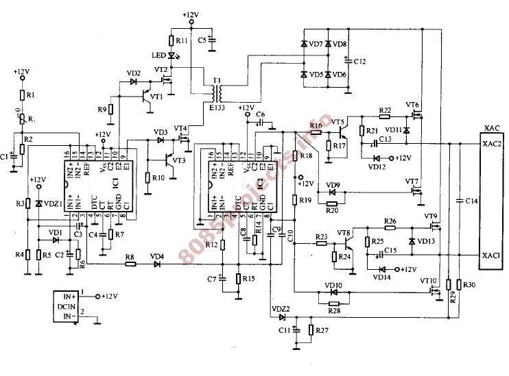
A schematic for an H-bridge circuit is required to convert a 350V DC input into a 230V AC output at a frequency of 50Hz. The design should utilize a 555 timer integrated circuit (IC) along with MOSFETs. An H-bridge is...
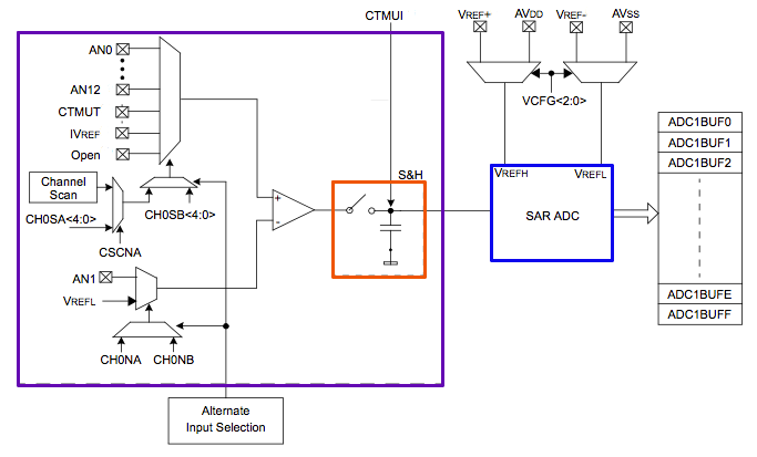
The PIC32's Analog to Digital Converter (ADC) can be challenging to configure for first-time users. The extensive range of configuration options available for the PIC peripherals can be overwhelming. This tutorial aims to assist users in navigating these complexities. The...
The HandyBoard operates both pads using the positive supply from the battery. When one of the motors is intended to turn, the HandyBoard activates the corresponding pin to 0V. The voltage difference between the two pads causes the motor...
It was previously assumed that dynamic braking would be most effective at higher speeds. However, tests conducted with a Faulhaber (Micro Mo) gear motor demonstrated that the brake could hold the motor almost stationary. These gear motors are constructed...
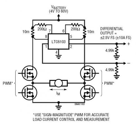
The dual outputs of the LTC6103 can be utilized independently for overload detection or combined as a differential pair to provide a bidirectional signal to an analog-to-digital converter (ADC). A typical circuit for a generic H-bridge application is illustrated....
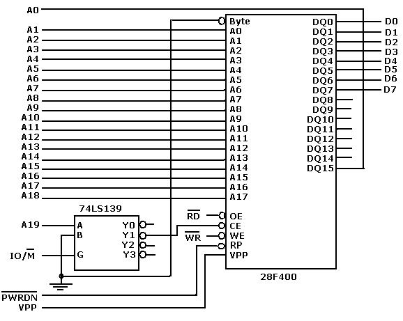
Flash memory, also known as flash RAM, is a type of non-volatile semiconductor memory device that retains stored data even when not powered. It is an enhanced version of electrically erasable programmable read-only memory (EEPROM). The primary distinction between...