
Half-bridge circuit

The selection of switch mode power supply (SMPS) topologies for applications such as solid-state Tesla coils (SSTCs) is critical for achieving reliability and performance. Among the various topologies, the full-bridge and half-bridge configurations stand out despite their initial complexity. A full-bridge topology employs four switches arranged in a bridge configuration, allowing for bidirectional current flow through the load, which is particularly advantageous in applications requiring high efficiency and power handling.
The gate drive transformer plays a crucial role in isolating the control circuitry from the high-voltage output and ensuring that the MOSFETs are turned on and off efficiently. Proper design of this transformer, along with the associated drive circuit, is essential for minimizing losses and preventing overheating. Additionally, the inclusion of extra diodes around the MOSFETs serves to protect against voltage spikes that can occur during operation, further enhancing the reliability of the circuit.
The half-bridge topology simplifies the design by using only two switches, making it a more compact solution while still providing the necessary performance for many applications. Both topologies allow for frequency modulation, which is vital for maintaining control over the output frequency and preventing instability that can lead to component failure.
The challenges associated with RF PCB layout and gate drive transformer design are significant but manageable. A well-optimized PCB layout minimizes parasitic inductance and capacitance, which can adversely affect performance at high frequencies. Additionally, careful attention must be paid to component placement and grounding to reduce noise and improve the overall efficiency of the system.
While other topologies exist, such as push-pull and flyback, they often introduce complexities that can lead to operational difficulties, especially at higher power levels. These alternative designs may require sophisticated control mechanisms to maintain stability and prevent damage, making them less suitable for applications where simplicity and reliability are paramount.
The OLTC, introduced by Terry Fritz, represents an innovative approach to Tesla coil design, combining the principles of SMPS with the unique requirements of Tesla coils. By eliminating the need for high-voltage transformers and utilizing IGBTs, this topology simplifies the overall design while maintaining high performance. The OLTC's ability to operate with a freely oscillating resonant load further enhances its versatility in various applications.
In conclusion, the full-bridge and half-bridge topologies provide robust solutions for SMPS in SSTC applications, balancing complexity with performance and reliability. The ongoing exploration of new topologies, such as the OLTC, continues to expand the possibilities within this field, offering engineers a variety of options to suit their specific needs.Which switch mode power supply (SMPS) topology should one start with IMHO although the schematic of a full-bridge looks a bit complicated compared to push-pull and half-bridge designs, sticking straight to a full-bridge topology or its smaller version, the half-bridge, is absolutely worth the initial extra effort. (Simplified schematic, gate drive transformer and drive circuit as well as the required extra diodes around the mosfets, and capacitor equalizing resistors are not shown) In the end, despite the more complex look of these topologies, there`s really much less that can go wrong when compared to the various troubles that come up in other topologies like push-pull, forward converter variants, flyback, etc The main "challenges" in the SSTC design process are to make a good RF PCB layout, and to properly design the gate drive transformer. Both can take some time to get finished. The rest of the circuit is very easy to build. Why only these four topologies The main reason is that all of them can be manually (or automatically) tuned in output frequency, without this SMPS/SSTC running completely out of control.
Of course there exist other topologies too. Actually there`s a HUGE variety of topologies and their small variations, so it is maybe tens hundreds even thousands Jeez, who invented them all. ;) These other topologies are either very complex, or require careful supervision by a dedicated fast controller IC so that nothing blows up, or they run only at a fixed frequency, or for some other reason won`t work so well in power (>100W ) SSTC use.
Then again, if you`ve found a promising SMPS topology that might easily work in SSTCs too, feel free to correct me ( jwagner@cc. hut. fi ), or mayber better, suggest it on the Tesla coil mailing list Update: in `03 Terry Fritz devised a new semi-SSTC type of silicon controlled TC, the OLTC (off-line Tesla coil).
It reminds a bit of an off-line buck boost converter with a freely oscillating resonant load. The OLTC runs without any HV transformers, and uses a single IGBT switch (or parelleled IGBT`s) to replace the spark gap. Steve Conner [scopeboy] has more infos at OLTC FAQ 1. 0 and working OLTC designs. 🔗 External reference
Related Circuits
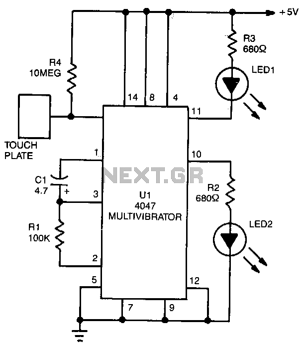
LED1 and LED2 indicators activate and stay illuminated each time the circuit is triggered. During the timing cycle, the Q output at pin 10 of U1 becomes positive when the Q output at pin 11 turns negative. The two...
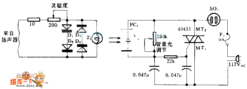
When the circuit is connected to hi-fi equipment or at both ends of the electronic instrument's speaker, the audio level can be modulated to a 500W lamp proportionally. This is achieved using three appropriate sets of audio filters and...
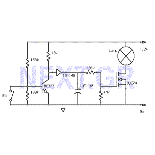
This circuit gradually switches the internal lights of a car on and off. The delay time can be adjusted by changing the values of the 10k and 4.7M resistors, as well as the capacitor. The circuit operates by utilizing a...
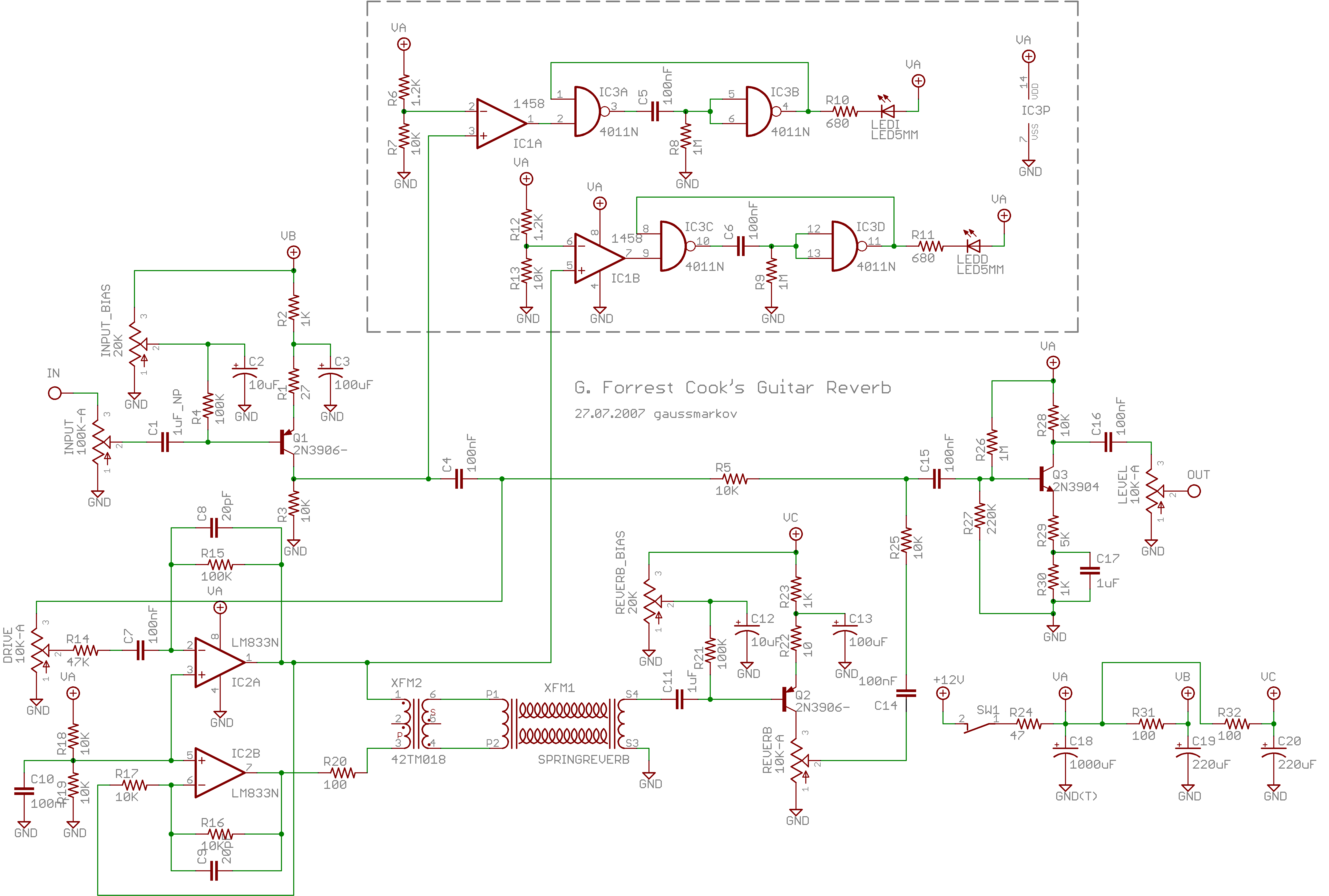
Spring reverb produces a clean and natural sound, often perceived as exceptionally good for a spring reverb. However, when the reverb springs are struck forcefully, they create explosive dub-like effects. Spring reverb is an analog sound processing technique that utilizes...

This design circuit is for audio graphic equalizers, which are commonly found in commercial products, yet circuits for them are rarely published. The circuit features a simple design that requires an operational amplifier (op-amp) to amplify the input signal....
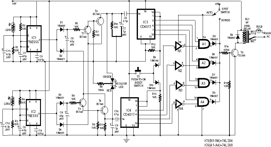
The circuit employs two Light Dependent Resistors (LDRs) arranged in series with a separation of approximately half a meter. This configuration allows each LDR to detect the presence of a person entering or exiting the room. The processed outputs...