
Light circuit diagram: Audio Graphic Equalizer Circuit Using Op Amp

The audio graphic equalizer circuit is designed to manipulate audio signals across multiple frequency bands, allowing users to enhance or attenuate specific frequencies according to their preferences. The heart of the circuit is the operational amplifier, which serves as the primary amplification stage. The inclusion of gyrators in the design allows for the emulation of inductive behavior without the need for physical inductors, which can be bulky and expensive. Each gyrator stage is configured to create a bandpass filter, with the center frequency and quality factor adjustable through the selection of capacitors and resistors.
The operational amplifier may be configured in a non-inverting mode to ensure that the output signal remains in phase with the input signal, providing a clean amplification of the audio input. The gyrator's functionality is enhanced by the interaction between the resistors and capacitors, which defines the frequency response of each band. The three formulas included in the circuit design are crucial for understanding and optimizing its performance. The center frequency formula allows for precise tuning of each band, while the Q factor formula aids in determining the bandwidth of the filter. The impedance formula is essential for assessing how the circuit interacts with the connected audio components, ensuring compatibility and optimal performance.
In summary, this audio graphic equalizer circuit design emphasizes simplicity and effectiveness, utilizing operational amplifiers and gyrators to create a versatile tool for audio processing. The design's flexibility in adjusting frequency response and quality factors makes it suitable for various audio applications, from home audio systems to professional sound equipment.This is a design circuit for audio graphic equalizers, that are very common as commercial products but circuits for them are very rarely published. This circuit is a simple design circuit. The circuit is need an op-amp for amplifying the input signal. This is the figure of the circuit. Only one gyrator stage is shown: all 7 gyrators are the same c ircuit, only the capacitors change, as shown in the chart. I have shown three of the seven faders to show where they go. A gyrator is a circuit using active devices and transistors to simulate an inductor. In this case the gyrator is the transistor acting with R1, R3 and C2. It could just as easily be a unity gain op-amp. The circuit includes three formulae: one which gives f, the the centre frequency of the band. The second shows how the Q is related to the capacitor ratio. The third shows the impedance presented by the circuit. Note that this includes 3 terms, the first purely resistive, the second is the capacitive contribution from C1 and the third is an inductive term from the gyrator. 🔗 External reference
Related Circuits
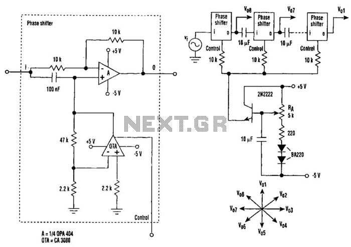
The circuit consists of eight cascaded identical cells, each cell being a DC-controlled active phase shifter. Since the DC control is common for all shifters, the circuit is adjusted by tuning resistor RA so that the phase difference between...
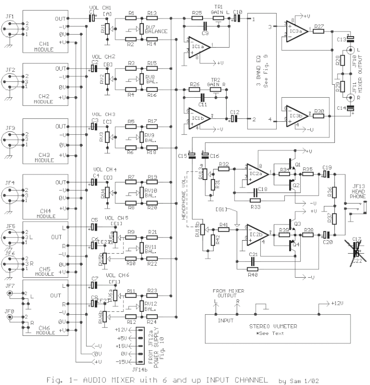
The circuit was designed to create an audio mixer that can be assembled in modules while providing 6 or more input channels. An audio mixer is a device used to combine multiple audio signals into a single output. The audio...
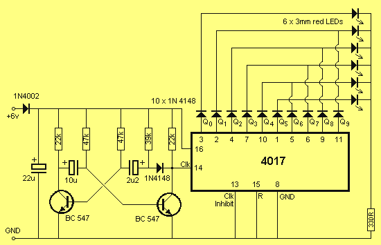
The circuit consists of two building blocks. The first is a square wave oscillator made up of two transistors in a multivibrator arrangement and the second is a CD 4017 decade counter IC. The multivibrator contains two extra components...
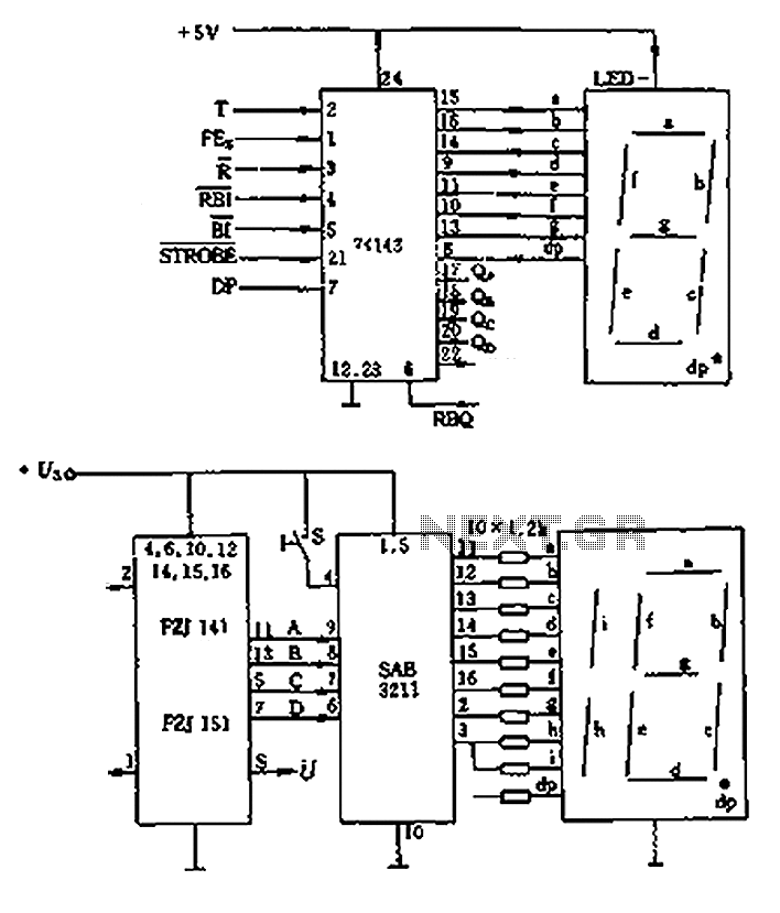
The decimal seven-segment storage decoding drive unit 74HC143 provides a constant output for all segments, each at a voltage of 5V and a current ranging from approximately 15mA to 22mA. The BCD data for the seven-segment decoder can be...
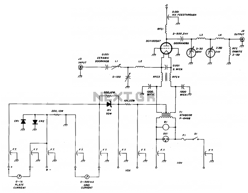
The amplifier utilizes a grounded grid circuit featuring either the Eimac 3CX1000A7 or 8877 ceramic/metal triodes designed for linear operation within the HF and VHF frequency ranges. It delivers a legal power output of 1500 watts PEP and continuous...
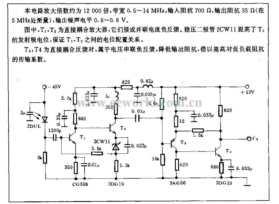
The amplification of this circuit is approximately 12,000 times, with a bandwidth ranging from 0.5 to 14 MHz. The input resistance is 700 ohms, while the output resistance is 35 ohms (measured at 5 MHz). The output noise level...