
Half wave AC phase-controlled circuit

The circuit described involves a triggering mechanism utilizing two capacitors, each rated at 0 µF, which serve to control the voltage applied to a lamp. The triggering point is defined by the breakdown voltage of the lamp, indicating that once the voltage across the capacitors reaches this threshold, the circuit will activate, allowing current to flow and illuminating the lamp.
The control feature of this circuit allows for a variable output, enabling the user to adjust the brightness of the lamp from a completely off state to a maximum of 95% of the half-wave RMS output voltage. This is particularly useful in applications where dimming capabilities are required or where precise control over light output is necessary.
Furthermore, the circuit can be enhanced by incorporating a switch in parallel with the silicon-controlled rectifier (SCR). This addition allows for full power operation, bypassing the SCR when the switch is closed. In this configuration, the SCR can be used for dimming purposes while the switch provides an option for full brightness when needed. The design of the circuit should take into account the specifications of the SCR, ensuring it can handle the required current and voltage levels without overheating or failing.
The overall schematic will consist of the two capacitors, the lamp, the SCR, and the switch. Proper attention should be given to the ratings of all components to ensure reliability and safety during operation. Additionally, it is advisable to implement protective components such as fuses or circuit breakers to prevent damage due to overcurrent conditions.The 5AH will trigger when the voltage across the two 0 juF capacitors reaches the breakdown voltage of the lamp. Control can be obtained full off to 95% of the half wave RMS output voltage Full power can be obtained with the addition of the switch across the SCR.
Related Circuits
This FM spy transmitter can function as a bug transmitter or a DIY FM bug. It utilizes a single IC 74F13, one coil, a capacitor, and one additional component. The FM spy transmitter is a compact device designed for covert...
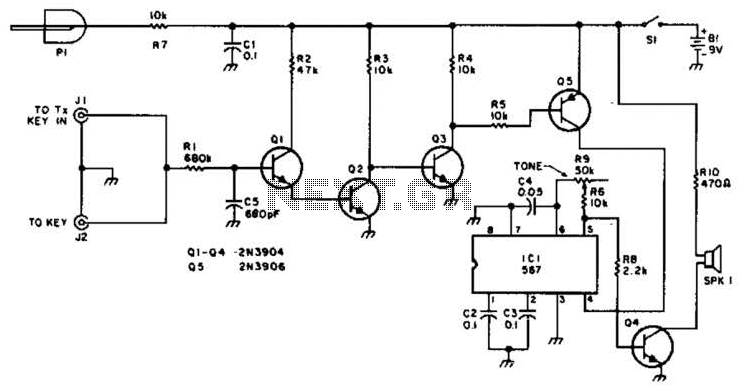
For use with low-power transmitters that require a positive keying voltage. The transistors Q1, Q2, and Q3 are configured as a switching amplifier. When the key is pressed, the collector of Q3 is pulled to ground, which activates Q5...
Over 1400 top electronics projects and electronic circuits with photos, datasheets, and easy-to-read schematics, along with explanations of how they work and how to build them. The collection comprises a vast array of electronics projects suitable for enthusiasts and professionals...

The Clock Controller was designed as an exemplary application of the C programming language to manage timer0 interrupts, control a 7-segment LED display, and perform keypad scanning. It offers a 1-bit sink current output suitable for driving devices such...
Here is a handy zener diode tester which tests zener diodes with breakdown voltages extending up to 120 volts. The main advantage of this circuit is that it works with a voltage as low as 6V DC and consumes...

TDA7262 stereo 20 watts audio amplifier circuit design electronic project The TDA7262 is an integrated circuit designed for stereo audio amplification, capable of delivering up to 20 watts per channel. This amplifier circuit is suitable for various applications, including home...