
Zener tester circuit

The zener diode tester circuit operates by utilizing a transformer, typically designed for 230V AC input, which is connected in reverse to generate a high AC voltage output. The use of a BC547 transistor as an oscillator allows for the modulation of the input voltage, effectively driving the transformer to produce the necessary output voltage. The circuit requires minimal power, functioning efficiently at a low input voltage of 6V DC, while drawing less than 8 mA of current. This efficiency makes it suitable for portable applications, as it can comfortably fit within a 9V battery box.
The output from the transformer is rectified using a diode (D1) and smoothed with a filter capacitor (C2) to provide a stable DC voltage for testing zener diodes. The current limiting resistor (R3) ensures that the circuit does not exceed safe current levels, protecting both the circuit and the zener diode during testing.
To operate the tester, the user must first verify the DC voltage across points A and B without any connected zener diode. This initial check is crucial, as it ensures the circuit is functioning correctly and can provide a variable DC output ranging from 10V to 120V, controlled by the adjustable potentiometer (VR1).
When testing a zener diode, the diode is connected across points A and B with the cathode connected to point A. The user then adjusts VR1 to maximize the DC voltage across the points, allowing for accurate measurement of the zener breakdown voltage. It should be noted that the circuit is optimized for zener diodes with breakdown voltages above 5.8V, as readings for diodes below this threshold may be inaccurate. In cases where the zener diode is shorted, the multimeter will indicate a voltage of 0V, signaling a fault in the component being tested.
This zener diode tester is a practical tool for electronics enthusiasts and professionals, offering a straightforward method for testing zener diodes across a wide voltage range while maintaining a compact and efficient design. Here is a handy zener diode tester which tests zener diodes with breakdown voltages extending up to 120 volts. The main advantage of this circuit is that it works with a voltage as low as 6V DC and consumes less than 8 mA current.
The circuit can be fitted in a 9V battery box. Two-third of the box may be used for four 1.5V batteries and the remaining one-third is sufficient for accommodating this circuit. In this circuit a commonly available transformer with 230V AC primary to 9-0-9V, 500mA secondary is used in reverse to achieve higher AC voltage across 230V AC terminals.
Transistor T1 (BC547) is configured as an oscillator and driver to obtain required AC voltage across transformer`s 230V AC terminals. This AC voltage is converted to DC by diode D1 and filter capacitor C2 and is used to test the zener diodes. R3 is used as a seri- es current limiting resistor. After assembling the circuit, check DC voltage across points A and B without connecting any zener diode.
Now switch on S1. The DC voltage across A-B should vary from 10V to 120V by adjusting potmeter VR1 (10k). If every thing is all right, the circuit is ready for use. For testing a zener diode of unknown value, connect it across points A and B with cathode towards A. Adjust potmeter VR1 so as to obtain the maximum DC voltage across A and B. Note down this zener value corresponding to DC voltage reading on the digital multimeter. When testing zener diode of value less than 3.3V, the meter shows less voltage instead of the actual zener value. However, correct reading is obtained for zener diodes of value above 5.8V with a tolerance of 10%. In case zener diode shorts, the multimeter shows 0 volts 🔗 External reference
Related Circuits
The ability amplifier has remained functional since it was first introduced in 2002. It is not broken, so there is no reason to fix it. The accompanying photo shows a well-assembled board (known as M27). Utilizing TIP35/36C transistors, the...
The Motorola company's MC14440 CMOS integrated circuit is designed for timing and displaying calendar functions. It utilizes a 32.768 kHz NT cutting type quartz crystal along with fine-tune capacitance to generate time-based signals. The display circuit operates on a...
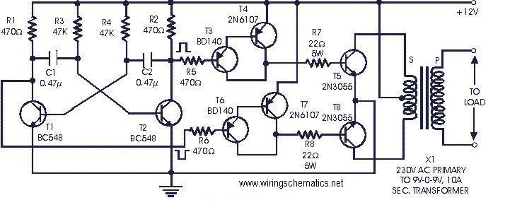
The following circuit is a cost-effective, fully transistorized inverter circuit suitable for driving medium loads in the range of 40 to 60 watts, operating with a 12V, 15 Ah battery or a larger power capacity. Transistors T1 and T2...
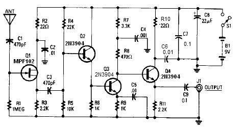
A simple active antenna can be designed using this electronic circuit diagram. This active antenna utilizes transistors and a few common electronic components. In the practice of short-wave frequency reception, a general rule is that a longer antenna will...
The schematic for an infrared burglar alarm circuit is depicted in Figure 1. The infrared transmitter operates as a multivibrator with an oscillation frequency of 40 kHz, utilizing the NE555 integrated circuit (IC2), along with resistors R1 and R2...

The moderate power FM transmitter circuit employs two transistors. The voice signals picked up by the microphone will be amplified by the transistor. The described FM transmitter circuit utilizes two transistors to facilitate the modulation and amplification of audio signals....