
HC132 Selling Leads

The described circuit functions as a protective mechanism for solid-state relays, primarily focusing on preventing damage due to overloads and short circuits. The operational sequence begins with the controlling pulse train generator (ptP), which initiates the flip-flop (IC1). The flip-flop's output controls transistor Q1, allowing current to flow through the relay's input, thus activating the relay to perform its intended function.
In the event of an overcurrent situation, the circuit is designed to detect excessive current through the sense resistor R5. When the current exceeds a predetermined threshold, it generates a voltage that activates one of the optoisolators (IC4A or IC4B). The optoisolator's output transistor effectively shunts the current away from the relay's input, limiting the amount of current that can pass through the relay's output. This action prevents potential damage to the relay and the connected load.
If the overload condition persists and the voltage across the sense resistor continues to rise, the optoisolator will trigger the Schmitt trigger, which is designed to provide a clean switching response. The Schmitt trigger's input is monitored closely, and once the voltage exceeds its threshold, it resets the flip-flop, which in turn deactivates the solid-state relay. This ensures that the load is disconnected during fault conditions, thereby protecting both the relay and the load.
Resistor R2 plays a critical role in maintaining the integrity of the circuit. It limits the voltage at the Schmitt trigger input to below 5 V, preventing latch-up conditions that could lead to erratic behavior. Additionally, in conjunction with capacitor C1, R2 forms an RC filter that smooths out any potential noise or voltage spikes, protecting the Schmitt trigger from false triggering events.
The output from the flip-flop can be utilized to communicate overload conditions back to the controlling pulse train generator, allowing for further action or monitoring. This circuit design integrates robust features that ensure reliable operation and protection of solid-state relays in various applications.The circuit protects a solid-state relay from overloads. The circuit limits current, automatically discon-nects the load after detecting a short circuit, and develops a fault-condition output signal. In normal operation, the controlling ptP sets the flip-flop, IC1, which turns on transistor Q1. When Q1 turns on, current flows through the solid-sta te relay`s input, thus activating the relay. If an overcurrent or fault condition occurs, the excessive load current flowing through the relay develops enough potential across sense resistor R5 to turn on one of the optoisolators, IC4A or IC4B. The optoisolator`s output transistor diverts current around the solid-state relay`s input, which limits the cur-rent that the relay`s output can pass.
If the overload is severe enough, the optoisolator pulls the input of the Schmitt trigger above its threshold, thus clearing the flip-flop and turning off the solid-state relay. R2 has two functions: It keeps the input of the Schmitt trigger below 5 V max. to prevent latchup, and it forms an RC filter in conjunction with C1. The RC filter prevents spurious triggering of the Schmitt trigger. You can use the output of the flip-flop to signal overload conditions to the controlling P. 🔗 External reference
Related Circuits
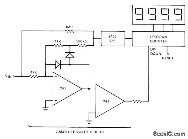
The absolute-value integrator circuit generates the effect of producing negative frequencies when the input signal is negative. It accomplishes this by allowing the counter to count up for positive voltage and count down for negative voltage. The specific types...
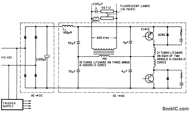
C141C datasheet. Selling leads from all over the world, ChinaICMart is the world's largest IC trading marketplace on the internet. It offers the best suppliers for C141C, and users can also download the datasheet for C141C. The C141C is an...
This circuit features a DS1236 component that monitors and controls the power supply and software execution of a processor-based system, while also providing a pushbutton reset function. An out-of-tolerance condition triggers the RST and RST outputs to enter the...
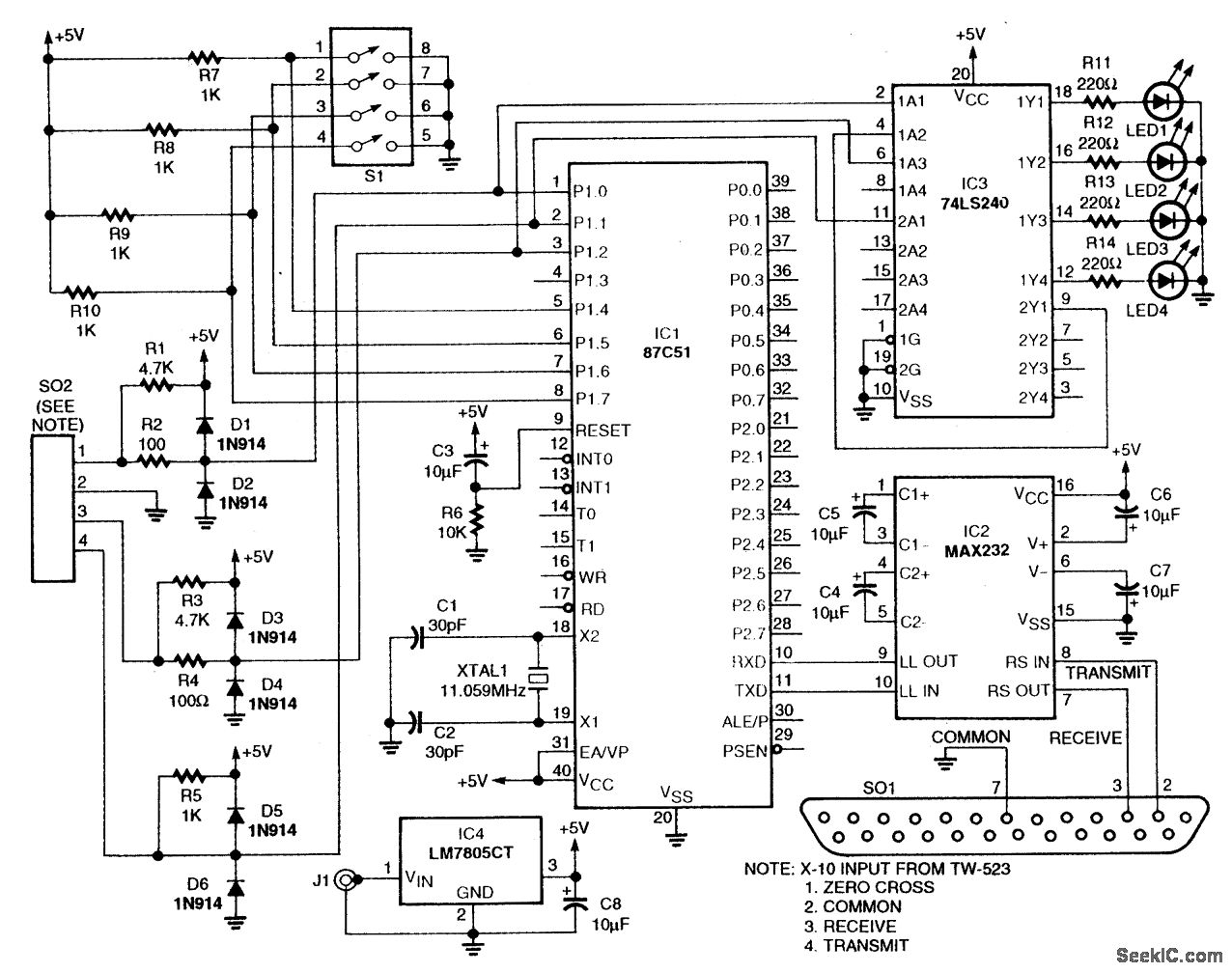
This circuit utilizes an 87C57 microcontroller along with several peripherals to convert X-10 power-line carrier-code formats from a personal computer for use with an X-10 power-line interface in a home control system. Software details can be found in the...
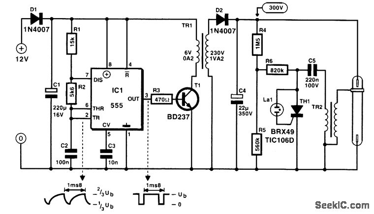
BD237 datasheet. Selling leads from all over the world, ChinaICMart is the world's largest IC trading marketplace on the internet. It offers the best suppliers for BD237, and users can also download the datasheet for BD237. The BD237 is a...
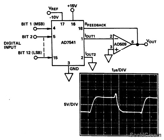
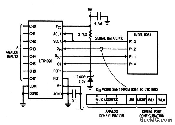
Special tabbed-resistor geometries improve time stability, while full input protection from damage due to static discharge is provided by diode clamps to V+ and ground. Additionally, large IOUT1 and IOUT2 bus lines enhance performance by reducing superposition errors. These...