
8051 Selling Leads

The DS1236 integrated circuit serves as a vital component in ensuring the reliability and stability of processor-based systems by monitoring power supply levels and software execution integrity. The key function of this circuit is its ability to detect voltage levels that fall below specified thresholds, which can indicate potential power supply issues. When the voltage at VCC drops below 4.5 V for 10% operation or below 4.75 V for 5% operation, the RST and RST outputs are activated to signal a fault condition. This is critical for maintaining system integrity, as it prevents the processor from operating under unstable conditions.
During the power-up sequence, a delay is implemented where the RST and RST outputs remain active for at least 25 ms, typically extending to 100 ms. This delay ensures that the power supply and processor have adequate time to stabilize before normal operation resumes. The debounced pushbutton reset input (PBRST) further enhances system reliability by providing a manual reset capability, which is also held active for a minimum of 25 ms, ensuring that transient glitches do not inadvertently reset the system.
The watchdog timer feature is particularly important in embedded systems where software execution must be monitored continuously. The ST input serves as a watchdog signal derived from various system signals, including address, data, and control lines. If the ST input does not receive stimulation within a predetermined timeframe—typically 400 ms, but no longer than 600 ms—the watchdog timer will activate the RST and RST outputs, effectively shutting down the processor. This mechanism is essential for preventing system hangs or crashes due to software failures, as it forces a reset and allows the system to recover from an unresponsive state.
Overall, the DS1236 circuit is designed to enhance the robustness and reliability of processor-based systems by providing critical monitoring and control functions, ensuring that the system operates within safe parameters while allowing for manual intervention and recovery from software failures.This circuit shows a DS1236 that is used to monitor and control the power-supply and software execution of a processor-based system, and to provide a pushbutton reset. When an out-of-tolerance condition occurs (when VCC is below 4. 5 V for 10% operation, or below 4. 75 V for 5% operation), the RST and RST outputs are driven to the active state. On p ower-up, RST and RST are held active for a minimum of 25 ms (100 ms typical) after 4. 5 V (or 4. 75 V) is reached to allow the power supply and processor to stabilize. The pushbutton input PBRST is debounced and timed so that reset signals are driven to the active state for 25 ms minimum. The watchdog-timer function forces RST and RST to the active state (shutting down the processor) when the ST input is not stimulated for a predetermined time period (because of some failure in software execution).
The watchdog time period is 400-ms typical (600-ms maximum). The ST input can be taken from address, data, and/or control signals. When the processing is executing software, these signals are present, and cause the watchdog to be reset prior to time-out. Dallas Semiconductors, Product Data Book, 1992/1993, p. 10-73. 🔗 External reference
Related Circuits
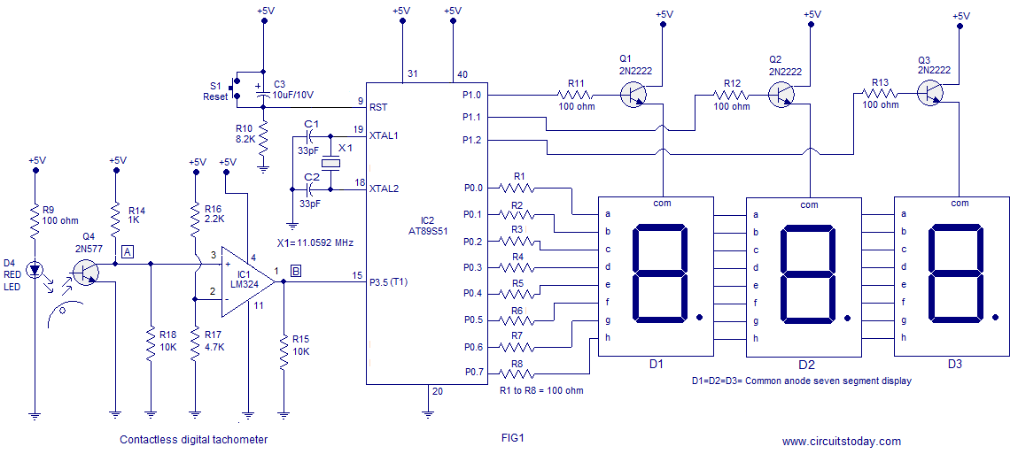
A three-digit contactless digital tachometer utilizing an 8051 microcontroller is presented for measuring the revolutions per second of rotating objects such as wheels, discs, or shafts. The tachometer can measure up to a maximum of 255 revolutions per second...
The traffic light controller section consists of 12 point LEDs arranged in 4 lanes on the PS/8051 Trainer Kit. Each lane features a Go (Green), Listen (Yellow), and Stop (Red) LED. The PS-8051 board demonstrates the capabilities of the...
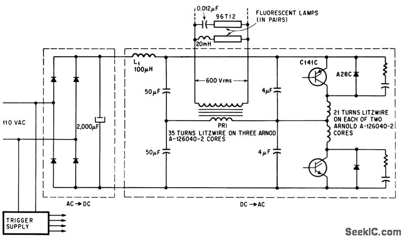
C141C datasheet. Selling leads from all over the world, ChinaICMart is the world's largest IC trading marketplace on the internet. It offers the best suppliers for C141C, and users can also download the datasheet for C141C. The C141C is an...
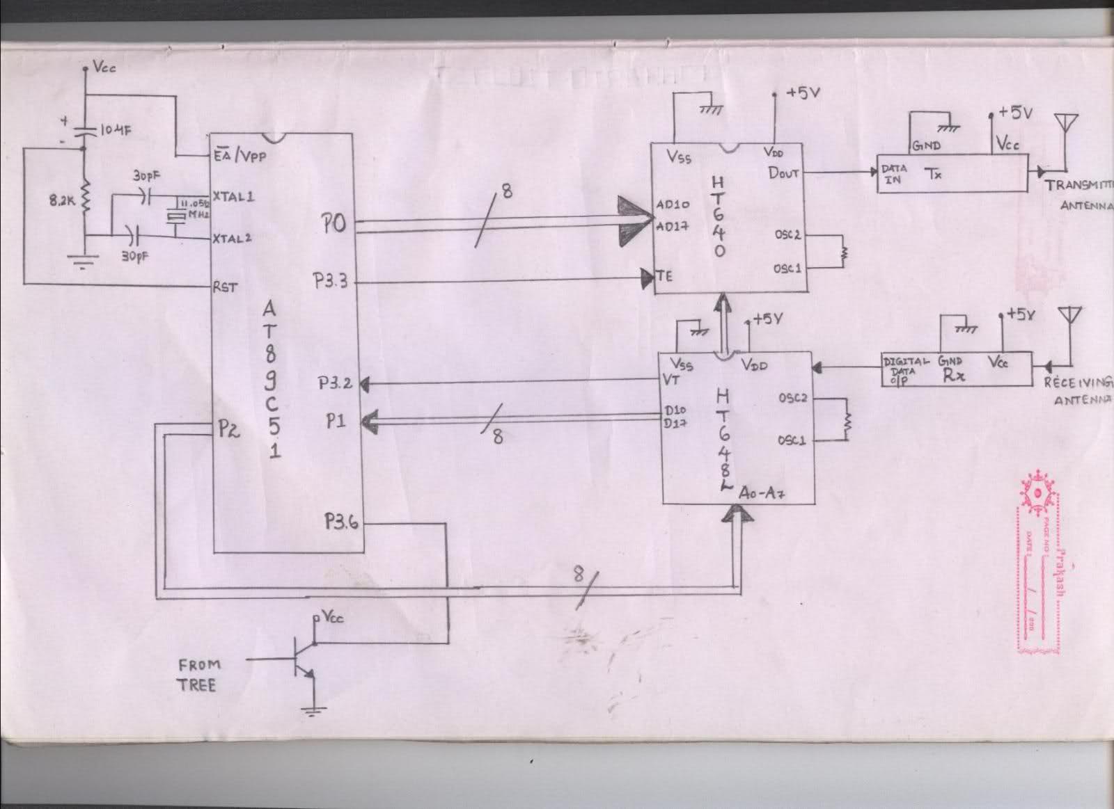
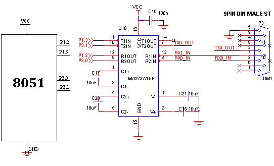
The issue arises when connecting the 8051 microcontroller to the HT640 encoder; the data sent is not received at the receiver. However, when the connections to the 8051 are removed, the transmission functions perfectly. This indicates that manual RF...
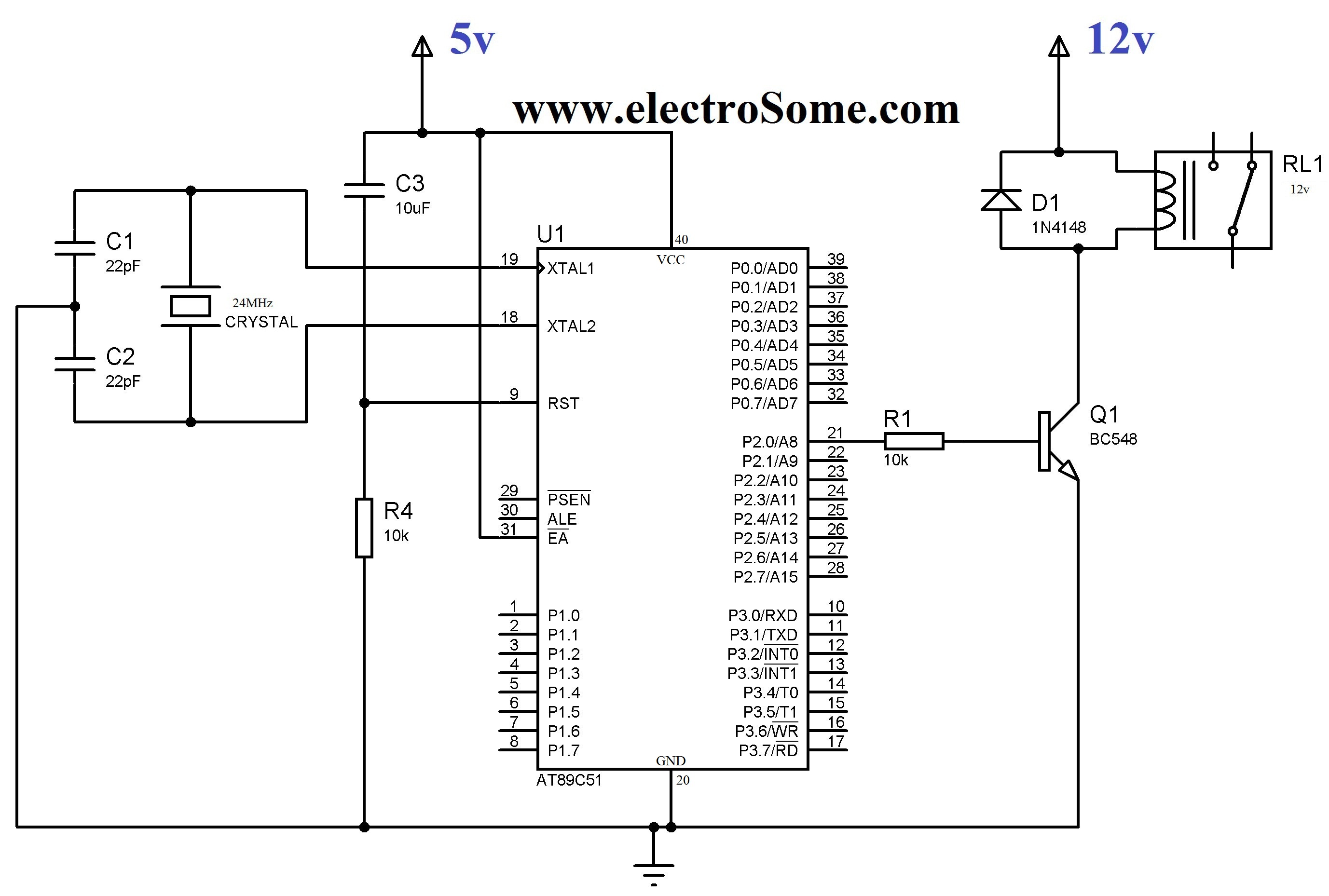
In various electronic applications, it is necessary to switch or control high voltages or high currents. In such instances, electromagnetic or solid-state relays may be utilized. For example, these relays can control home appliances using low-power electronic circuits. An...
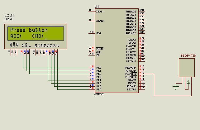
Infrared light is electromagnetic radiation with longer wavelengths than those of visible light. It is utilized in various industrial, scientific, and medical applications. Most remote controllers employ infrared light to transmit information. This protocol was developed by Philips using...