
Head phone amplifier circuit

The headphone amplifier circuit operates by first amplifying the weak audio signal from the music player using the Q1 transistor. The BC 239 transistor is configured as a common emitter amplifier, which provides voltage gain. The input audio signal is applied to the base of Q1, and the amplified output is taken from the collector. The feedback mechanism through resistor R3 is crucial as it stabilizes the gain and reduces harmonic distortion, leading to a cleaner audio output.
Following the preamplification stage, the output signal is sent to the driver stage formed by Q2 and Q3 transistors. The BC 337 and BC 327 transistors are configured in a push-pull arrangement, allowing for efficient driving of the headphones. This configuration helps to deliver the necessary current to the headphones, ensuring that they are adequately powered for optimal sound reproduction.
The power supply for this circuit should be carefully selected to match the voltage requirements of the transistors, typically ranging from 9V to 12V. Proper bypass capacitors should be included to filter out any power supply noise, ensuring that the amplifier delivers a clean audio signal.
Overall, this headphone amplifier circuit is an effective solution for enhancing audio output from devices that may not provide sufficient power, utilizing a minimal number of components while achieving high performance.Here is a simple head phone amplifier circuit that can be used to drive your head phone if your music player doesn`t have enough power to drive your head phones. The circuit is straight forward and uses only three transistors. The transistor Q1 (BC 239) and associated components forms a pre amplifier. The transistor pairs Q2 & Q3 (BC 337 & BC 327) f orms the driver circuit for the speaker. Power amplification is attained at this stage. The emitter voltage of Q1 is fed back to base of Q1 via R3 in order to improve performance and reduce distortion. 🔗 External reference
Related Circuits
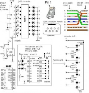
A LAN tester circuit diagram is presented in two designs. The first design utilizes a timer IC 555 and a decade counter 4017. The second design employs a microcontroller ATtiny2313. The first design of the LAN tester circuit incorporates the...
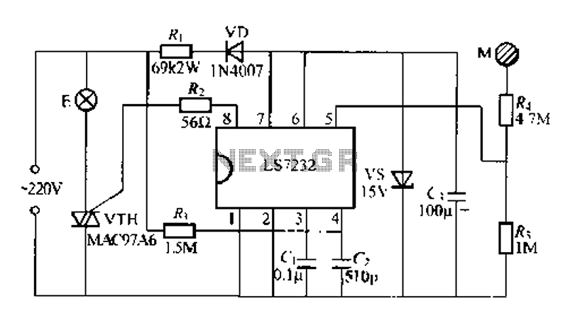
Figure (a) illustrates a general inverting amplifier circuit, which includes a 100k potentiometer as a feedback resistor connected in series between the input terminal and the inverting input to compensate for the DC bias current. The potentiometer (Rp) should...
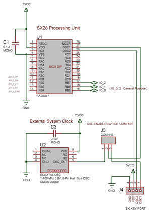
The SX 28 internal oscillator is not that fast, so an external oscillator can be hooked up to the processor as shown in the diagram to increase the operation cycles per second. The SX 28 microcontroller is designed with an...
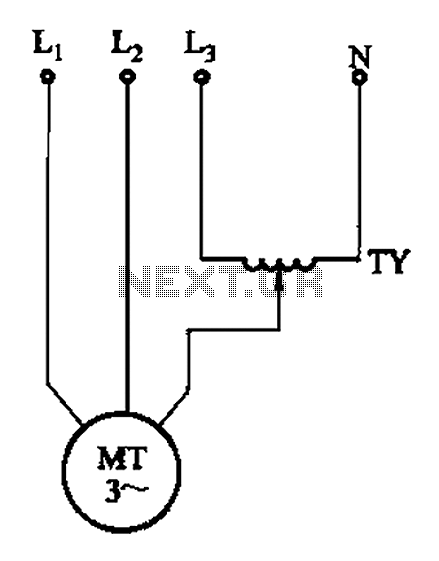
The circuit illustrated in Figure 3-175 features a regulator connected between one phase and neutral. It is designed for use with a 380V torque motor. This method offers advantages over the serious line imbalance approach, resulting in improved operating...
The following circuit illustrates a USB Powered Audio Power Amplifier Circuit Diagram. Features include multimedia speakers for PCs and a single-chip-based design. The USB Powered Audio Power Amplifier Circuit is designed to enhance audio output for multimedia speakers connected to...

This circuit is designed to measure the inductance of an inductor labeled LX. The output of the circuit generates a TTL square wave, with its frequency being directly related to the inductance being measured. The output from the inductance...