
Headlight Flasher

The circuit operates by employing the NE555 timer in astable mode, which allows it to generate a continuous square wave output. This output is connected to a relay that controls the headlights, enabling them to turn on and off at a specified frequency. The frequency of the flashing can be adjusted by changing the resistor and capacitor values connected to the timer.
In a typical setup, the circuit includes the NE555 timer IC, a few passive components such as resistors and capacitors, and a relay capable of handling the current drawn by the headlights. The NE555 timer is powered by the vehicle's battery, ensuring that it operates effectively even when the vehicle is stationary.
The use of the relay is crucial as it isolates the low-power timer circuit from the high-power headlights, preventing any potential damage to the timer IC. The circuit can be further enhanced with additional features such as a variable resistor to adjust the flashing rate, or diodes to protect against back EMF generated by the relay.
Overall, this circuit serves as an engaging project for automotive enthusiasts, providing a practical application of the NE555 timer while enhancing vehicle visibility through the flashing headlights.Small and interesting circuit that flashes your head lights. Automotive, head lights, circuit diagram. Built around famous NE555 timer circuit.. 🔗 External reference
Related Circuits
This device is a simple timer that keeps the headlights of a vehicle on for approximately 1 minute and 30 seconds, allowing access to dark areas without the need to manually switch off the lights. Activating switch P1 initiates...
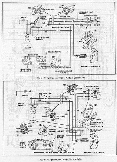
The system operates solely on vacuum. Upon inspection of the vacuum hoses, two brittle hoses were found that ran through the firewall to the headlight switch, where a slight hissing sound was noticeable when the lights were activated. Touching...

Many published circuits that flash LEDs require 3 volts or more. This circuit utilizes a single inexpensive C-MOS IC and can flash an LED for an entire year on a single 1.5-volt AA alkaline battery cell. The circuit employs...
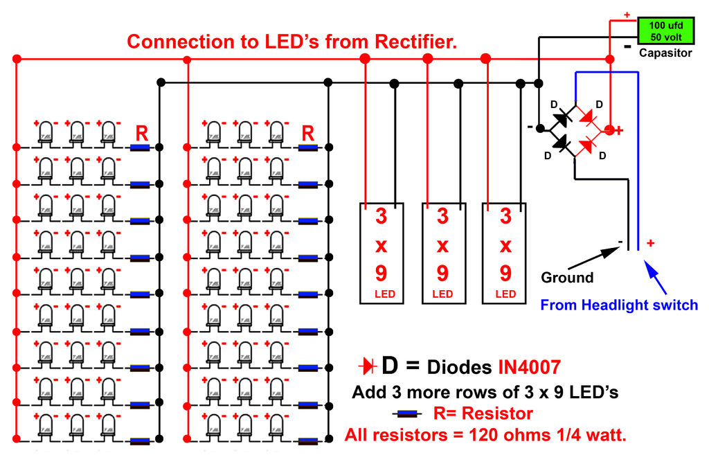
Gently bend the leads of the LEDs and, using the provided schematic circuit diagram, begin to solder. Once soldering is complete, it should... To successfully assemble the LED circuit, it is essential to follow a systematic approach. Start by preparing...
The concept of this economical flashing LED indicator is straightforward. It employs a low-frequency oscillator to drive two LEDs connected in anti-parallel. In the circuit diagram, it can be observed that the current flows for a brief duration with...
A bike equipped with a 35-watt HS1 bulb is being upgraded to a brighter headlight using an H4 60/65-watt xenon bulb. An expert recommended using relays due to the increased power requirements of the new bulb. Research conducted on...