
motorcycle headlight with single spdt relay

To wire an H4 xenon bulb using a single 30-amp SPDT relay, the following components and connections are required:
1. **Components**:
- H4 60/65-watt xenon bulb
- 30-amp SPDT relay
- 30-amp fuse holder with appropriate fuse
- Wiring (16 AWG or thicker is recommended for high current)
- Connectors and terminals as needed
2. **Relay Pin Configuration**:
- Pin 85: Relay coil negative (ground)
- Pin 86: Relay coil positive (trigger)
- Pin 30: Common terminal (input power)
- Pin 87: Normally open (NO) terminal (high beam)
- Pin 87a: Normally closed (NC) terminal (low beam)
3. **Wiring Steps**:
- Connect the battery positive terminal to the fuse holder and then to pin 30 of the relay. Use a fuse rated for 30 amps to protect the circuit.
- Connect pin 87 of the relay to the high beam terminal of the H4 xenon bulb.
- Connect pin 87a of the relay to the low beam terminal of the H4 bulb.
- Connect the ground terminal of the H4 bulb to the negative battery terminal or the bike's chassis.
- Connect pin 85 of the relay to the bike's ground.
- Connect pin 86 to the switch that will control the high/low beam function. This switch can be the original headlight switch of the bike. When the switch is in the high beam position, it will energize the relay and connect the high beam terminal to the power. In the low beam position, the relay will connect to the low beam terminal.
4. **Operation**:
- When the high beam is activated, the relay is energized, connecting power to the high beam terminal of the bulb.
- When the low beam is activated, the relay will switch to the low beam terminal, allowing the bulb to operate at a lower brightness.
A schematic diagram can be created based on these connections, ensuring that all wiring is secure and insulated to prevent shorts. This setup provides a reliable method to upgrade the headlight while managing the increased power requirements of the H4 xenon bulb effectively.A bike with 35 watt HS1 bulb and I want to upgrade brightness of headlight so I decided to put H4 60/65 watt xenon bulb. An expert on this forum suggested me to use relays as the new bulb requires more power. I did some google to understand relays and how to wire new headlight with relays, but the confusion is that the links and videos for relay wiring that I found online was for cars and car has two head lights
so they have used two SPDT(Bosch) relay for that but for my bike I need only one bulb so I guess single 30 AMP SPDT relay would be enough but I am confused what should be the circuit diagram for single SPDT relay to control headlight HI-LO beam. I know instead of making setup from scratch by myself many of you would suggest me to go for Eastern Beaver H4 kit but the problem is that I am in India and I dont have any paypal account to pay for kit and even not sure whether this kit would be economical for me or not thats why I decided to make this setup by myself.
I have 30amp SPDT relay, 30amp fuse holder and H4 xenon bulb and I need help of the experts on this forum to please guide me on how wire new headlight. A simple circuit diagram would be enough like this one at earlycuda. org: 🔗 External reference
Related Circuits
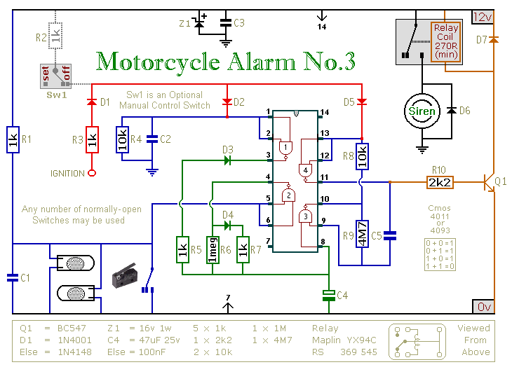
This circuit features an intermittent siren output and automatic reset. It can be operated manually using a key-switch or a hidden switch; but it can also be wired to set itself automatically when you turn-off the ignition. By adding...
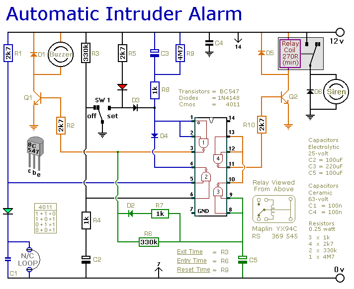
This is a simple single-zone home alarm system circuit. Its features include entry delays, a timed siren cut-off, and automatic exit. It is designed to be used with the usual types of normally-closed input devices such as foil tape,...
The most extreme option would be to supply power through a battery pack. A more plausible source would be the car's battery. However, since the objective of the circuit is to activate the buzzer when the headlights are on,...
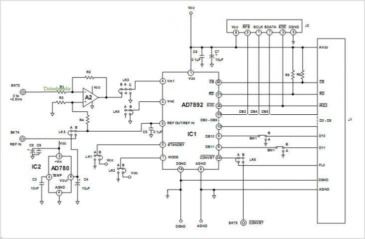
This data sheet describes the evaluation board for the AD9834 direct digital synthesizer (DDS). The AD9834 is a numerically controlled oscillator that utilizes a phase accumulator, a sine look-up table, and a 10-bit DAC. The AD9834 can operate with...

A relay is an electromechanical switch that operates by opening and closing under the control of another electric circuit. When current flows through the relay's coil, a magnetic field is generated, causing an armature to move, which either establishes...
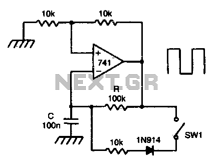
This circuit incorporates a Schmitt trigger and an integrator configured around a single operational amplifier (op-amp). The timing is regulated by an RC network. The voltage at the inverting input tracks the exponential charging of the capacitor within defined...