
Headlight Flasher Circuit

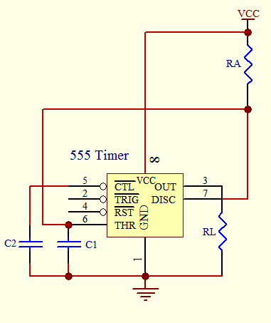
The headlight flasher circuit utilizes a 555 timer integrated circuit (IC) in an astable configuration to generate a square wave output. This output toggles the gate of an IRF53IND hexFET, allowing it to control the power delivered to a connected lamp. The 555 timer operates in an astable mode, where it continuously switches between high and low states, thereby generating a periodic signal with a frequency of 1 Hz.
The timing components, typically resistors and capacitors connected to the 555 timer, determine the frequency and duty cycle of the oscillation. In this configuration, the output pin of the 555 timer is connected to the gate of the IRF53IND, which is a type of MOSFET designed to handle high currents and voltages. The IRF53IND functions as a switch that opens and closes rapidly in response to the 555 timer's output, effectively turning the lamp on and off.
The circuit is powered by a suitable voltage source, and the lamp can be an automotive headlight or any other suitable load. The design ensures that the lamp flashes at a frequency of 1 Hz, providing a clear visual indication when activated. Proper heat dissipation measures should be considered for the IRF53IND, especially if it is controlling a load that draws significant current. Additionally, suitable protection components, such as diodes, may be included to protect the circuit from voltage spikes generated by the inductive load when switching.
This headlight flasher circuit is commonly used in automotive applications to enhance visibility and safety by providing a flashing light signal. It is a straightforward yet effective design that demonstrates the versatility of the 555 timer in various electronic applications. The headlight flasher is nothing more than a 555 oscillator/timer that`s configured as an astable multivibrator (oscillator). Its input is used to drive the gate of an IRF53IND hexFET, which, in turn, acts like an on/off switch,
turning the lamp on and off at the oscillating frequency (1 Hz).
Related Circuits

This simple-to-construct water fishing thermometer circuit is intended for use in sports applications, such as fishing contests. A sensor measures... This water fishing thermometer circuit is designed to provide accurate temperature readings of water, making it an essential tool for...

The circuit presented utilizes NAND logic gates from the Hitachi HD series, specifically the HD74LS00, which is a quad NAND integrated circuit. A special technique has been implemented to achieve three-state operation using a single IC. Gate N1 is...

Short circuits in the tracks, points, or wiring are nearly unavoidable when constructing or operating a model railway. Although transformers for model systems are designed with built-in bimetallic switches to protect against short circuits, the response time of these...

This system operates on the principle that the capacitance loading of an oscillator will lower its frequency. When a foreign body comes into contact with the touch plate, the frequency of U1 is lowered. This removes the oscillator signal...

This 2-meter 144 MHz fox hunt transmitter is utilized in amateur competitions where participants seek to locate a concealed transmitter using primarily homebrewed receivers. The 144 MHz fox hunt transmitter is designed for use in amateur radio competitions, commonly referred...
The timer circuit is utilized in various projects and is primarily categorized into two types. The first type is an analog RC circuit, where the charging of the capacitor determines the timing of the circuit. This type has a...