
Fishing Thermometer Project Circuit

This water fishing thermometer circuit is designed to provide accurate temperature readings of water, making it an essential tool for anglers during fishing contests. The circuit typically consists of a temperature sensor, such as a thermistor or an LM35, which is submerged in the water to measure the temperature.
The output from the temperature sensor is an analog voltage signal that corresponds to the temperature. This signal is then fed into an analog-to-digital converter (ADC) if a microcontroller is used, allowing for digital processing and display. The microcontroller can be programmed to display the temperature readings on an LCD screen or send the data wirelessly to a smartphone app for real-time monitoring.
In terms of construction, the circuit requires a power source, which can be a battery for portability. The components should be housed in a waterproof enclosure to protect them from water damage. Additionally, calibration of the temperature sensor may be necessary to ensure accurate readings, which can be done using known temperature references.
Overall, this circuit not only enhances the fishing experience by providing vital information about water temperature but also offers an educational opportunity for those interested in electronics and sensor applications in outdoor sports.This simple to construct water fishing thermometer circuit is intended to be used in sports applications like for example a fishing contest. A sensor measu.. 🔗 External reference
Related Circuits

This circuit is activated when switch SW1 is pressed, grounding the base of transistor Q2. The pulse rate is approximately equal to 0.7 multiplied by the product of resistor R3 and capacitor C1. The described circuit features a transistor Q2,...
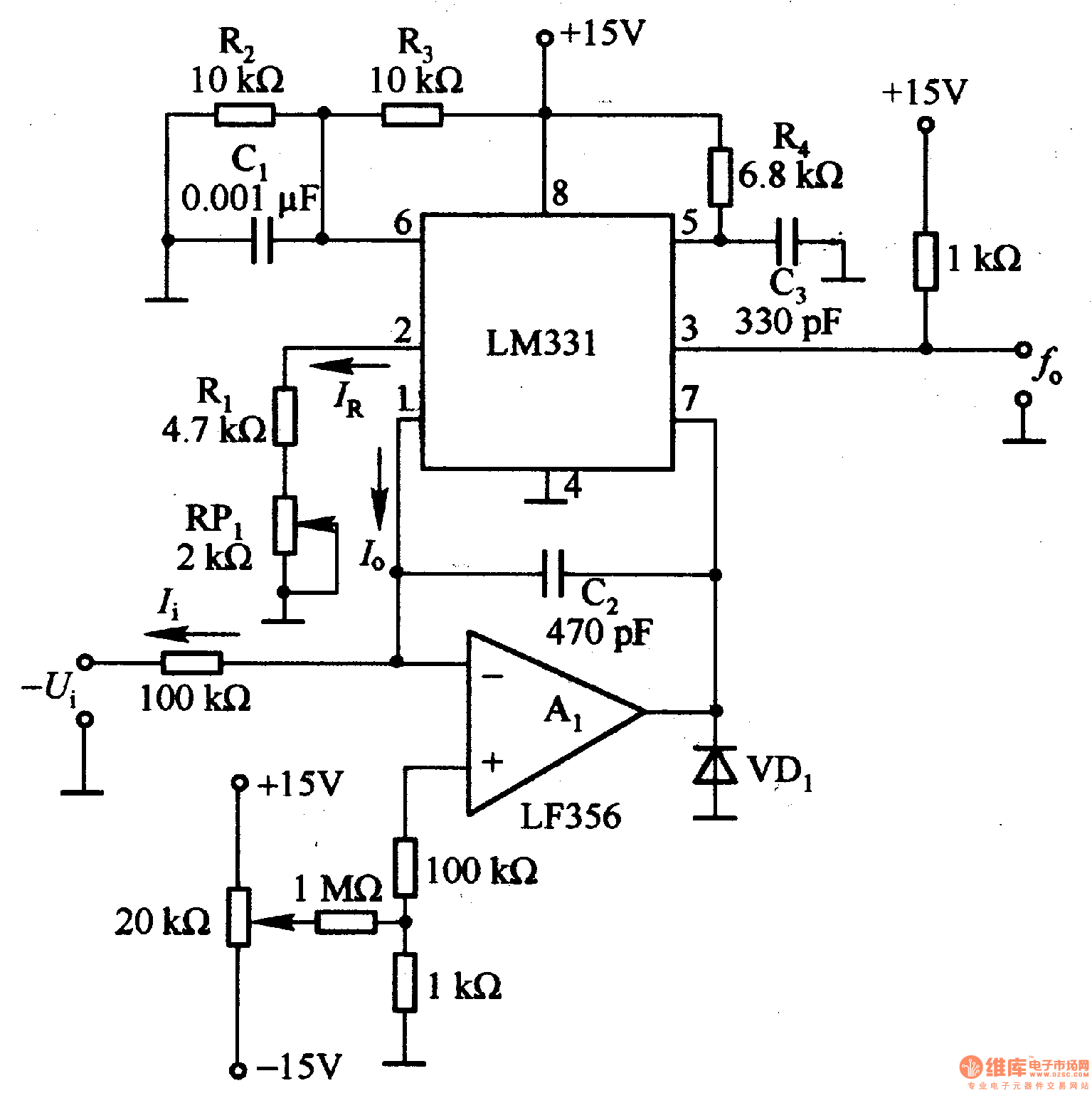
The LM331 is a single voltage-to-frequency conversion integrated circuit (IC) that includes a 1.9 V reference voltage, a current switch, a comparator, and a flip-flop. To expand its operational range, an A1 operational amplifier is added to the circuit....
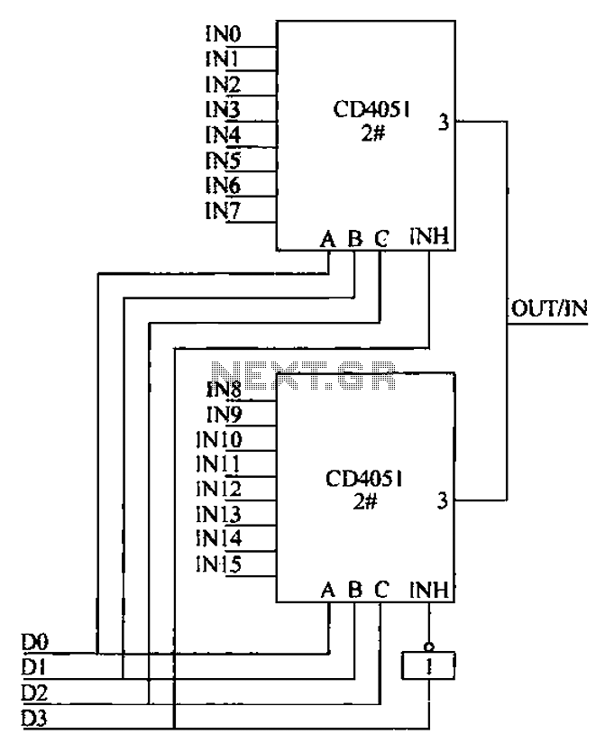
The CD4051 is a single-ended input 8-channel multiplexer that features three channel select inputs (A, B, C) and an inhibit input (INH). The signals at inputs A, B, and C are utilized to control the selection of one of...

The Joule thief circuit is well-known among electronics enthusiasts. It has numerous implementations, but the most common is a very minimalist voltage booster. In the simulation file, a 1.5V battery is attached, which is the voltage of a new...
Grounding the blue wire at the headlamp switch causes the lights to illuminate, indicating a faulty switch. Continuity of the switch has already been verified. The relay consists of two small terminals and two larger ones. The smaller terminal,...

The 20-W + 20-W stereo amplifier consists of two complete, separate 20-W RMS bridge-type amplifiers. The input signal source is brought into the amplifier through a voltage divider network, which is composed of resistors R1, R2, and potentiometer P1....