
Headlight Flasher with 555

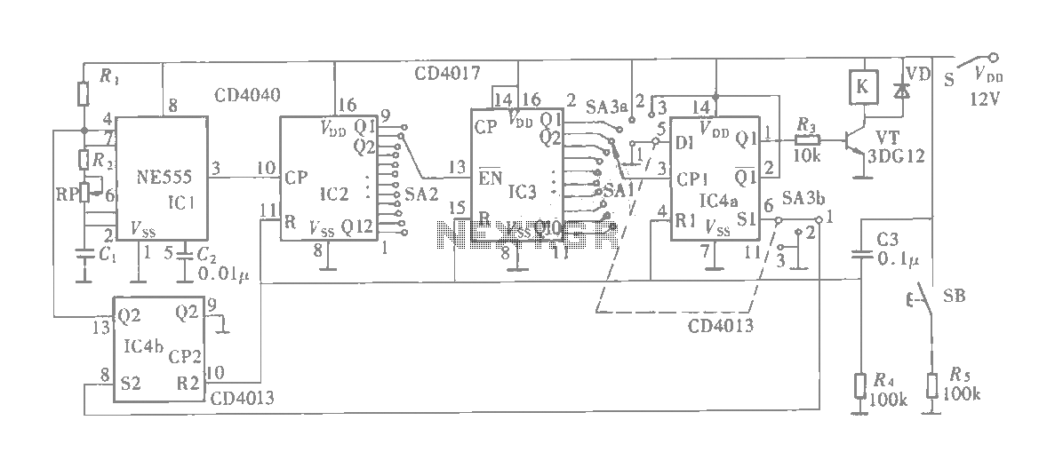
The described circuit utilizes a 555 timer integrated circuit configured in astable mode to achieve a flashing headlight effect for automotive applications. In this configuration, the 555 timer oscillates between high and low output states, generating a square wave signal that controls the operation of relays responsible for the headlight flashing.
The frequency of the flashing can be adjusted by varying the resistance of R1, which influences the charge and discharge times of the timing capacitor connected to the 555 timer. This flexibility allows for customization of the flash duration according to user preferences.
To integrate this circuit into a vehicle's headlight system, it is essential to identify the positive lead from the fuse box that supplies power to the headlights. This wire must be cut, and a relay contact should be inserted in series to control the power flow to the headlights based on the output from the 555 timer. The inclusion of a bypass switch in the circuit enables the user to revert to standard headlight operation without the flashing feature, providing convenience and safety.
For the alternating headlight flashing configuration, each headlight's positive wire must be severed, and additional relay contacts must be connected to control each headlight independently. This setup allows for a dynamic flashing effect, enhancing visibility and signaling capabilities while driving.
Overall, this circuit design offers a practical solution for automotive lighting customization, leveraging the capabilities of the 555 timer and relay systems to achieve desired headlight functionalities. Proper implementation requires careful attention to wiring and safety protocols to ensure reliable operation within the vehicle's electrical system.is circuit was requested from an email. It will allow your car headlights to flash on and off at the same time or it will cause them to flash alternately. The circuit is based on the 555 timer. It is used in the astable mode. The 555 timer output will go high for an adjustable period of time and then turn off. It will then repeat the procedure. The time is adjusted by R1. To hook up the circuit to your car you must locate the positive wire from the fuse box to the headlights.
Cut the wire and insert the relay contact and bypass switch. The bypass switch will allow you to bypass the relay contact for normal headlight operation. In the alternating headlight configuration you must cut the positive wire to each headlight and wire in the relay contact. 🔗 External reference
Related Circuits
Standard LED flashers activate the LED in a rapid on-off sequence, which can become bothersome over time. The circuit presented here offers a more gradual illumination effect. This circuit utilizes a simple design to create a soft flashing LED effect,...
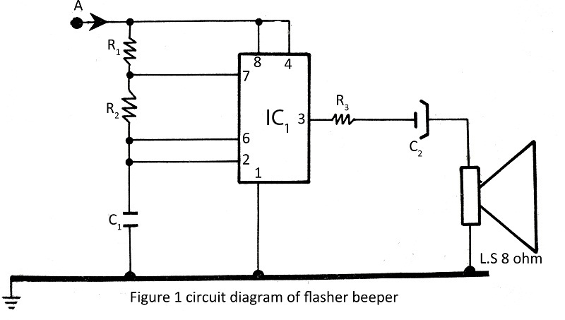
A flasher with a beeper is very easy to build and assemble. The flasher with a beeper is constructed using very common components, with various projects utilizing the NE555 timer IC. The flasher circuit typically employs the NE555 timer IC...
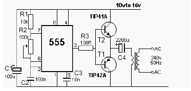
This 12V power inverter circuit can be utilized to supply power to small devices that require 240 volts. It is particularly beneficial when there is a need to operate equipment designed for 240 volts. The 12V power inverter circuit is...
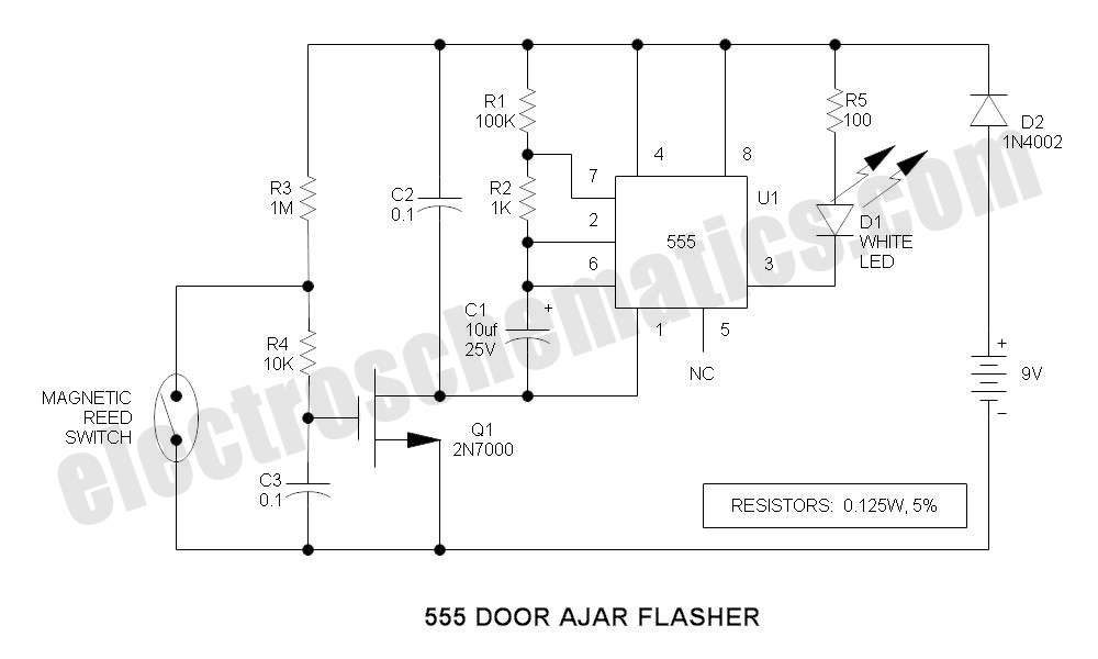
A magnet is positioned on the door, while a magnetic reed switch is installed on the door casing. When the door is closed, the circuit is disabled. When the door is opened, the circuit becomes active. In this circuit design,...
The multifunction circuit primarily refers to its capability to operate in three modes: "delayed pull," "time release," and "delayed cycle." The term "delay" indicates that the relay is energized after a predetermined time; however, the relay does not activate...
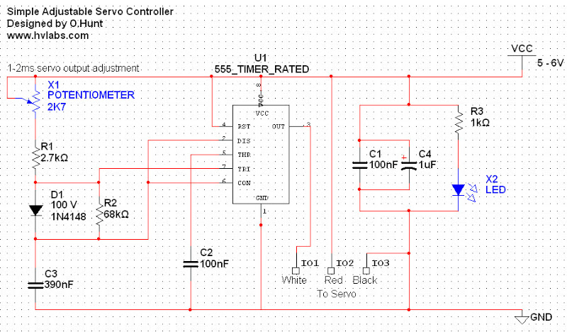
Servos are valuable components for various applications, including robotics, automation, and remote control tasks, such as steering model vehicles. They are relatively inexpensive and readily available; however, controlling them can be somewhat challenging as they require specific timing to...