
12V Power Inverter Using 555

The 12V power inverter circuit is designed to convert a 12V DC input into a 240V AC output, making it suitable for powering various small electrical devices that typically operate on standard AC voltage. The circuit generally consists of several key components, including a DC-DC converter, an oscillator, a transformer, and an output stage.
The DC-DC converter steps up the 12V input to a higher DC voltage, which is then fed into an oscillator circuit. This oscillator generates a high-frequency square wave signal, which is crucial for driving the transformer. The transformer is responsible for stepping up the voltage to the desired 240V AC level.
In many designs, the inverter may also include a feedback mechanism to regulate the output voltage and ensure stability under varying load conditions. Additional components such as capacitors and inductors may be used to filter the output waveform, improving the quality of the AC signal and reducing harmonic distortion.
Protection features are often integrated into the circuit to safeguard against overloads, short circuits, and thermal issues. These can include fuses, thermal cutoff switches, and current sensing circuits.
Overall, this 12V power inverter circuit is an efficient solution for converting low-voltage DC power into high-voltage AC power, enabling the use of various electrical devices in off-grid or mobile applications.This 12V power inverter circuit can be used to power small power devices that need a 240 volts. It is very useful when you want to use a 240 volts consume.. 🔗 External reference
Related Circuits
In this fire alarm circuit, a thermistor functions as the heat sensor. As the temperature rises, its resistance diminishes, and conversely, when the temperature falls, its resistance increases. At standard temperature, the resistance of the thermistor (TH1) is approximately...
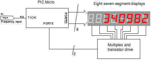
The circuit employs a straightforward approach for direct frequency measurement, which is user-friendly but results in the number of displayed digits varying with the input frequency. To consistently display all digits, a method known as reciprocal counting can be...
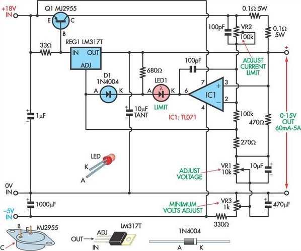
This circuit, based on a National Semiconductor application note, utilizes an LM317 3-terminal regulator (REG1) due to its integrated over-current and over-temperature protection features. The output current is amplified to slightly over 5A using the MJ2955 transistor (Q1). The...
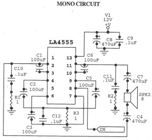
The following circuit illustrates an audio amplifier mono circuit diagram. This circuit is based on the LA4555 integrated circuit (IC). Features include a mono configuration and a power output of 2.3 watts. The audio amplifier circuit utilizing the LA4555 IC...
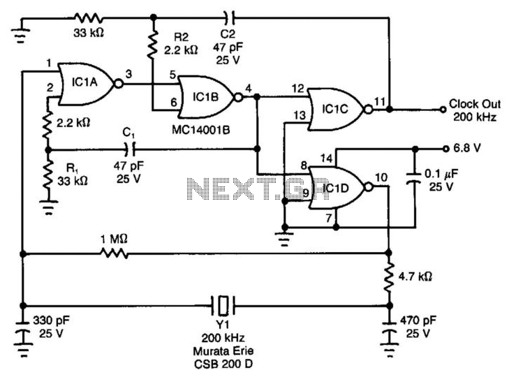
Ceramic resonators are suitable for low-power, low-frequency clock sources, despite their 30-ppm temperature coefficient. However, they exhibit troublesome spurious-resonance modes. This circuit effectively rejects all but the fundamental mode of the resonator. The clock circuit operates within a temperature...
Ensure that connections are verified against the circuit diagram and schematic provided below. This can be utilized while following the tutorial video. The circuit diagram serves as a crucial reference for accurately assembling electronic components in a project. It illustrates...