
headphone amplifier

The circuit design features two identical halves, ensuring consistent performance across both channels. Each input channel is equipped with a 47k dual logarithmic potentiometer that provides a DC path to ground. This configuration allows for precise control over the audio signal levels. The balance control, implemented as a linear potentiometer, enables users to adjust the relative volumes of the left and right channels. When centered, it delivers equal signal levels; however, shifting it to either side alters the resistance in the corresponding channel, effectively favoring one channel over the other.
The inclusion of 10k resistors before the inputs serves a protective function, preventing accidental short circuits to ground, which could damage the circuit components. The audio signal amplification is accomplished through a common emitter amplifier stage, which is known for its ability to provide significant voltage gain. This is followed by an emitter follower stage, which offers high input impedance and low output impedance, making it well-suited for driving headphones.
The circuit's overall gain is designed to be less than 10, which is sufficient for typical headphone listening levels. The emitter follower stage is capable of directly driving 8-ohm headphones, ensuring compatibility with standard audio devices. Higher impedance headphones can also be utilized effectively without loss of audio quality.
To mitigate any unwanted noise or transients, the circuit incorporates 2.2k resistors at each output. These resistors work in conjunction with the 2200µF coupling capacitors to block any DC offset that could cause audible "thump" sounds when connecting or disconnecting headphones. The self-biasing nature of the circuit allows it to function optimally across a range of power supply voltages, from 6 to 20 Volts DC, making it versatile for various applications in audio equipment. This design approach ensures reliable performance and user-friendly operation in a compact and efficient audio amplification circuit.Both halves of the circuit are identical. Both inputs have a dc path to ground via the input 47k control which should be a dual log type potentiometer. The balance control is a single 47k linear potentiometer, which at center adjustment prevents even attenuation to both left and right input signals.
If the balance control is moved towards the left side, the left input track has less resistance than the right track and the left channel is reduced more than the right side and vice versa. The preceding 10k resitors ensure that neither input can be "shorted" to earth. Amplification of the audio signal is provided by a single stage common emitter amplifier and then via a direct coupled emitter follower.
Overall gain is less than 10 but the final emitter follower stage will directly drive 8 ohm headphones. Higher impedance headphones will work equally well. Note the final 2k2 resistor at each output. This removes the dc potential from the 2200u coupling capacitors and prevents any "thump" being heard when headphones are plugged in.
The circuit is self biasing and designed to work with any power supply from 6 to 20 Volts DC. 🔗 External reference
Related Circuits
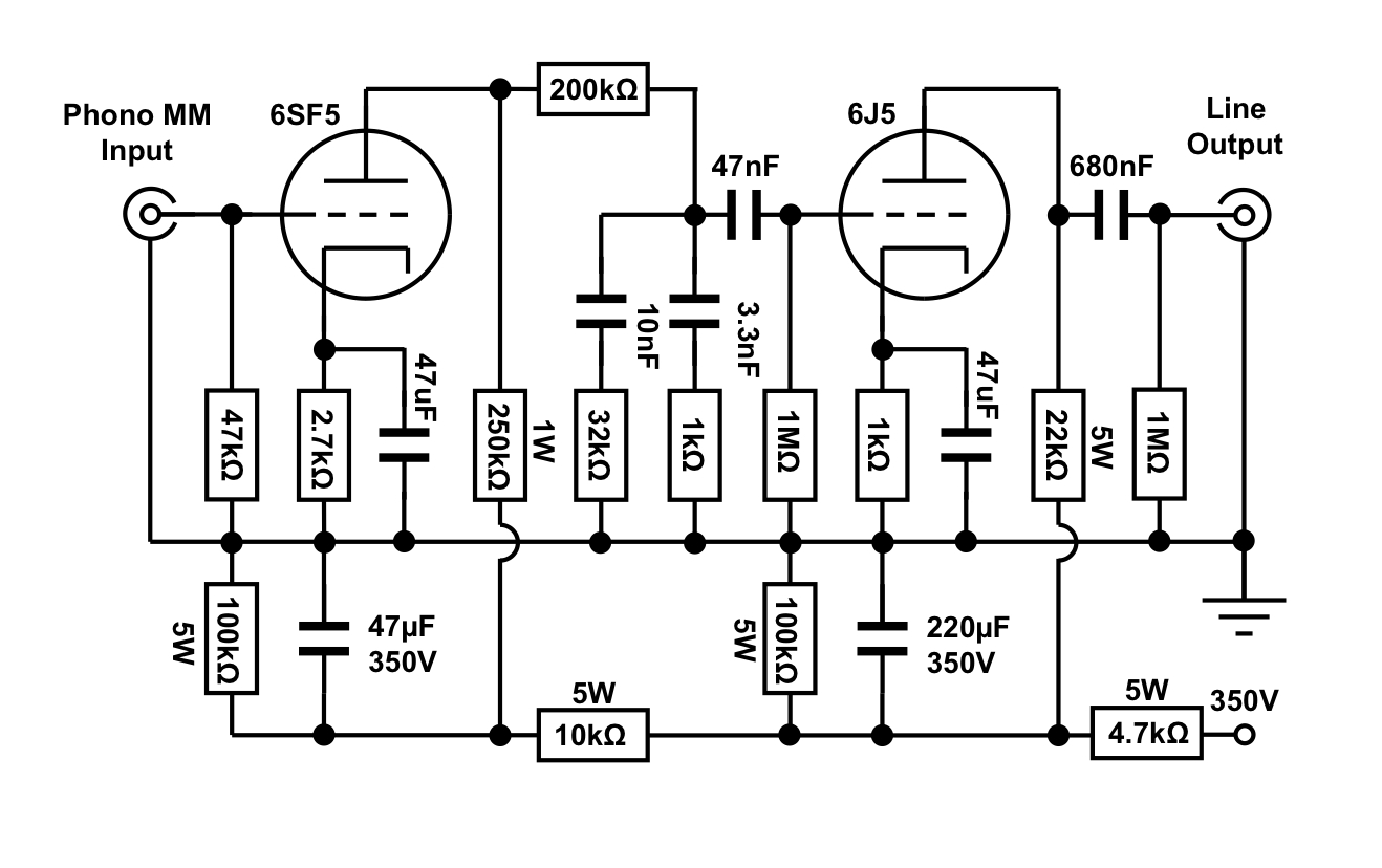
An octal preamplifier can be constructed as a standalone unit without the linestage component. However, this is not feasible due to its split RIAA configuration, which divides the RIAA equalization circuit into two sections: one following the first stage...
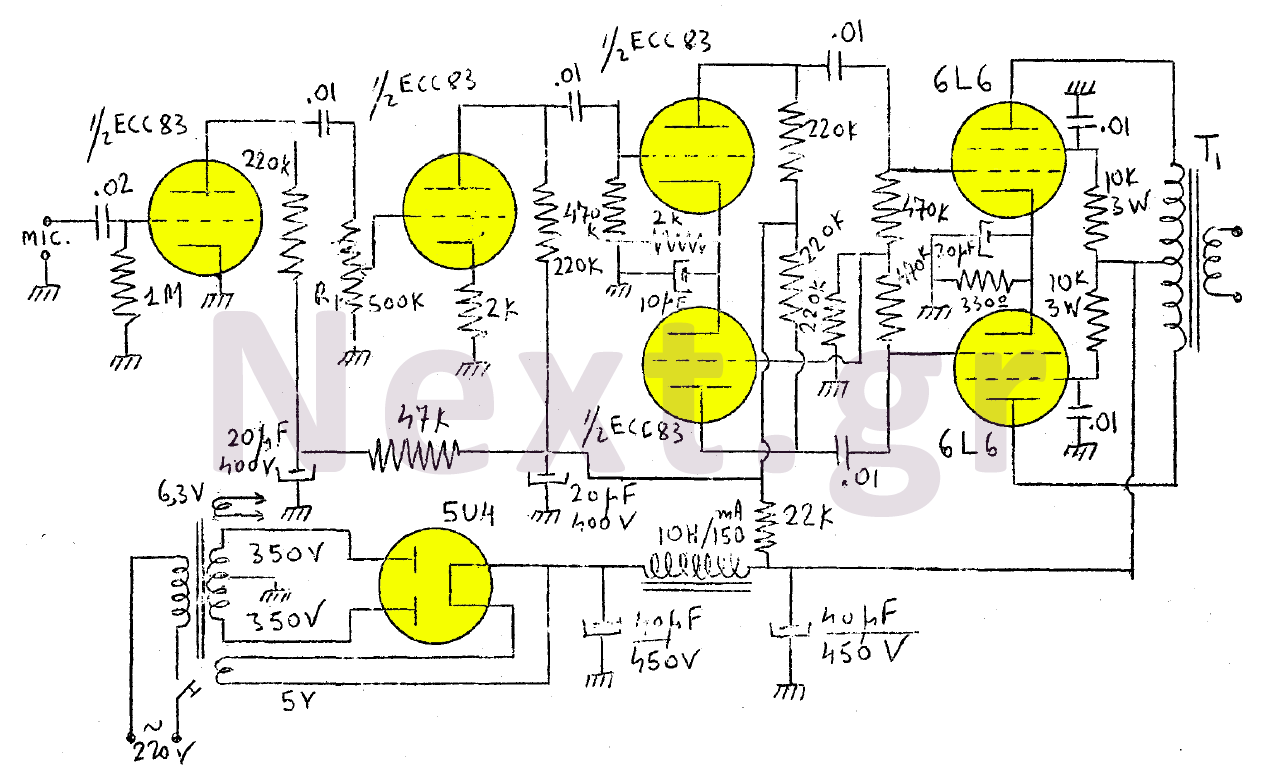
The amplifier in this design is rated at 30 Watts and is intended for use with a microphone. It is compatible with a crystal microphone and can be utilized for speeches, lectures, as a transmitter modulator, and in applications...
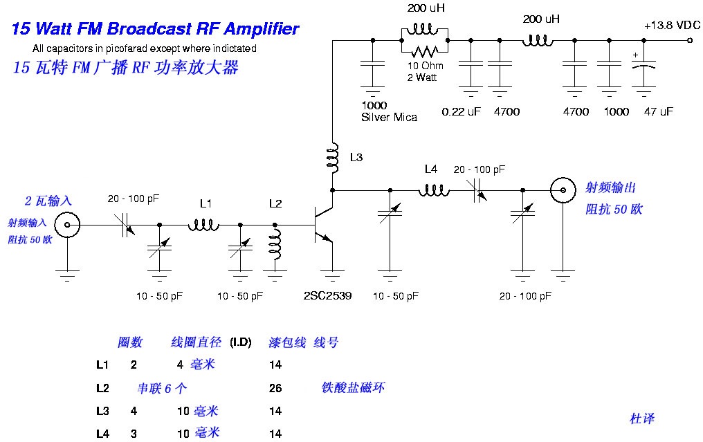
This FM broadcast RF amplifier is constructed using the 2SC2539, which is a silicon NPN epitaxial planar type transistor designed for RF power amplifiers in the VHF band. The FM broadcast RF amplifier utilizing the 2SC2539 transistor operates effectively within...
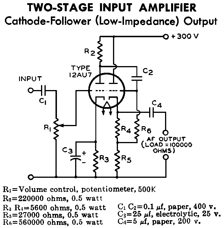
12AU7 (ECC82) Cathode Follower Tube Preamplifier Schematic. This is a two-stage 12AU7 preamplifier featuring a low impedance output stage. The overall gain is approximately 8 times. The 12AU7 (ECC82) tube is a dual triode commonly used in audio applications due...
This circuit deactivates an amplifier or any connected device when a low-level audio signal at its input is absent for at least 15 minutes. By pressing P1, the device is powered on, supplying power to any appliance connected to...
This complete high quality, low noise mono audio power amplifier is based around the Hybrid Integrated Circuit STK4050 manufactured by Sanyo. The circuit incorporates volume and has a maximum music output power of 200W. The circuit incorporates an on...