
2SC2539 FM RF Amplifier

The FM broadcast RF amplifier utilizing the 2SC2539 transistor operates effectively within the VHF frequency range, making it suitable for various applications in radio broadcasting. The 2SC2539 is known for its high gain and efficiency, which are critical parameters in RF amplification.
The circuit typically consists of a few key components: the 2SC2539 transistor, biasing resistors, coupling capacitors, and a power supply. The biasing resistors are essential for establishing the correct operating point of the transistor, ensuring it operates in the active region for linear amplification. Coupling capacitors are used to block DC while allowing the RF signal to pass through, maintaining signal integrity.
In addition, an output matching network may be included to optimize the power transfer from the transistor to the antenna, enhancing the overall performance of the amplifier. The design must consider factors such as load impedance and frequency response to achieve the desired output power and signal quality.
Proper heat dissipation measures, such as heat sinks, are also critical in maintaining the reliability of the 2SC2539 during operation, as RF amplifiers can generate significant heat. Overall, the design of this FM broadcast RF amplifier is a balance of component selection, circuit topology, and thermal management to achieve optimal performance in VHF applications.This FM broadcast rf amplifier is built with 2SC2539 which is a silicon NPN epitaxal planar type transistor designed for RF power amplifiers in VHF band mo.. 🔗 External reference
Related Circuits

A voltage comparator is a device that compares the voltages at its two inputs and generates an output based on the comparison. It produces a high output when the positive input exceeds the negative input and a low output...
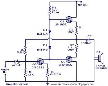
The initial section of the circuit is a preamplifier that utilizes transistor Q1 (2N2222). The collector of transistor Q3 is connected to the base of transistor Q2 (2N2905A), which creates a complementary symmetry pair with Q3 (2N3053). The amplified...
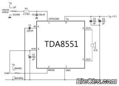
An amplifier with digital volume control can be designed predictably due to the simplicity of the circuit, which utilizes a single chip, the TDA8551. This series of mini amplifiers with digital volume control operates as a BTL (Bridge-Tied Load)...
This is a simple microphone preamplifier circuit which you can use between your microphone and stereo amplifier. This circuit amplifier microphone suitable for use with normal home stereo amplifier line/CD/aux/tape inputs. This mic preamp can take both dynamic and...
The RF amplifier is similar to the one used in the 2.5 MHz amplifier. At a frequency of 10 MHz, the capacitances of a power MOSFET become significant. Noiseless feedback using transformers is no longer straightforward. Intermodulation and overtones...
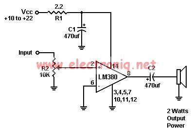
A simple audio amplifier can be designed using the LM380 along with a few external components. This amplifier features a wide supply voltage range, an input impedance of 150 kΩ, low distortion, and a current capability of 1.3 A. The...