
8W + 8W tube amplifier circuit

The VE1 preamplifier circuit is designed to provide high-quality audio amplification with minimal distortion. The use of a double triode 6N6 allows for effective signal processing in both audio channels, ensuring that stereo sound remains balanced and clear. The SRPP configuration is particularly beneficial for enhancing linearity and reducing harmonic distortion, making it suitable for high-fidelity audio applications.
The power supply architecture is critical to the performance of the VE1 preamplifier. The bridge rectifier (VD3 to VD6) converts the AC voltage from the city grid to a usable DC voltage, which is then filtered through capacitors C6 and C7 to smooth out the output. The +270V voltage is essential for the operation of the 6P3P tube, which serves as the output stage for the audio signal. The regulation provided by VT and VD11 ensures that fluctuations in the input voltage do not adversely affect the performance of the preamplifier.
The additional +250V supply for the anode is crucial for maintaining the operating point of the 6N6 tubes, allowing for optimal amplification without introducing noise. The design's secondary filtering stage, utilizing R7 and C5, generates a +200V supply for the SRPP configuration, which is vital for maintaining the integrity of the audio signal.
The filament supply design, utilizing both a dedicated IC regulator and a separate winding from the transformer, ensures that the tubes receive stable heating voltage. This is important for extending the lifespan of the tubes and maintaining consistent audio performance. The overall layout of the power supply minimizes electromagnetic interference, which can be detrimental to audio quality.
In summary, the VE1 preamplifier is a sophisticated audio device that employs advanced tube technology and thoughtful power supply design to achieve high fidelity and low distortion. The integration of various components, from the rectifiers to the filtering capacitors, is meticulously planned to create an efficient and reliable audio amplification solution.Preamplifier VE1 the machine with low muscle low R double triode 6N6 (left and right audio channels each with its half). Working state design in the CPI. Promote the use of high-level VE2 households, low R-made tubes EN11J, electric low distortion all the way in the form of consensus and wide SRPP (Shunt Regulated Push groan ull) 6 final amplifier circuit VE3 taken directly from the tube anode power supply AC 220V City grid. Electricity through VD3 ~ VD6 bridge rectifier, C 6 C7 filtered after wave t to obtain + 270v voltage power pole tube 6P3P screen, screen grid power; + 270V fork by VT VD11.
VDZ produce the adjusted regulated + 250V power supply is pre-VE1 anode feed; + 2sov then by R 7, c 5 secondary filter is formed + 200v voltage SRPP circuits. This can be taken directly electrically Tsui simplify the power supply transformer TP TP t to reduce size, weight and production cost Zhuo very useful because there is no single-ended amplifier CMRR (common mode rejection) effect, and therefore the power supply requirements are relatively harsh.
therefore. Anode power supply with dual capacitor filter; in addition t after all filament current supply by q wherein front and push through IC (VA78H06) Regulators fed A filament; another group AC 12V, 2A winding through rectifier bridge VD ~ VD14 , C14 ~ C16 filter in X, Y terminals generate about 1 2.4V voltage two-channel amplifier tube filament power supply port power transformer TP using the "voice of the" finished product (5; OVA ~ 12vx 21220V)
Related Circuits
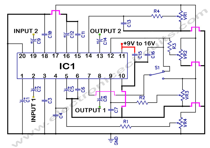
LM1036 Stereo Tone (Bass, Treble, Volume, Loudness, Balance) Controller Circuit. The LM1036 is a DC controlled tone (bass/treble), volume, and loudness controller designed for audio applications. The LM1036 circuit serves as an integrated solution for controlling various aspects of audio...
The following circuit illustrates a Mains Remote-Alert Circuit Diagram. Features include simple circuitry, with the transmitted signal being conveyed effectively. The Mains Remote-Alert Circuit is designed to provide a notification system that alerts users about the status of mains power....
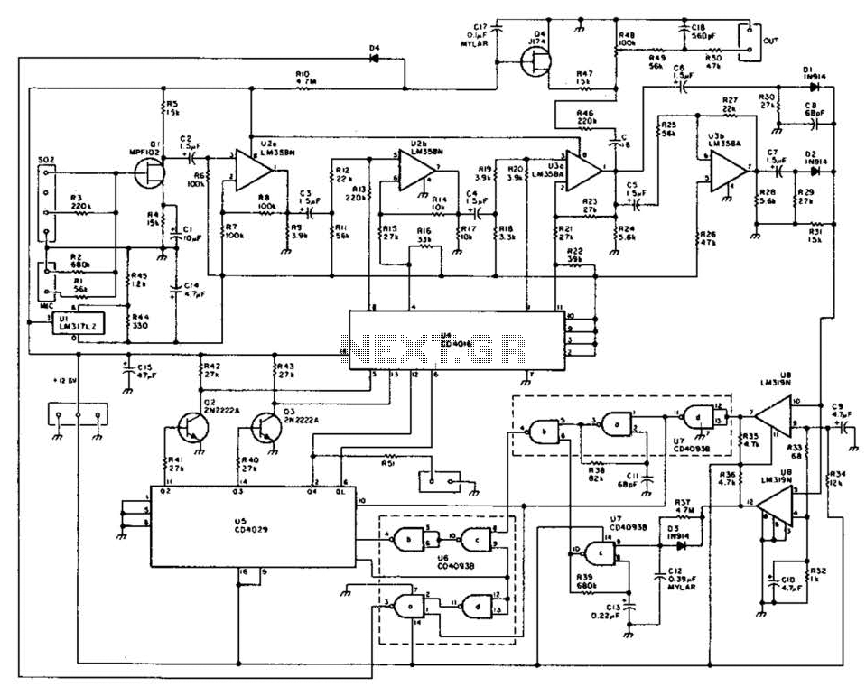
This method of automatic level control (ALC) utilizes digitally switched audio attenuators within the signal path. The output level of the system is monitored, compared to a reference level, and audio pads are introduced through analog switches. This technique...
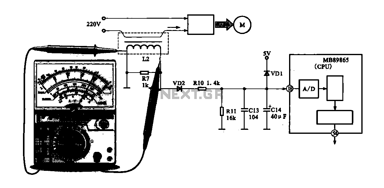
A current-voltage conversion circuit is commonly utilized in current detection applications. An example is the current detection circuit for a ring inverter air conditioner, which primarily serves to monitor the supply current of the compressor motor. Excessive current can...
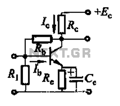
Basic reference transistor bias circuit - Mixed Negative feedback The basic reference transistor bias circuit utilizing mixed negative feedback is a fundamental electronic configuration designed to stabilize the operating point of a transistor. This circuit typically employs a combination of...
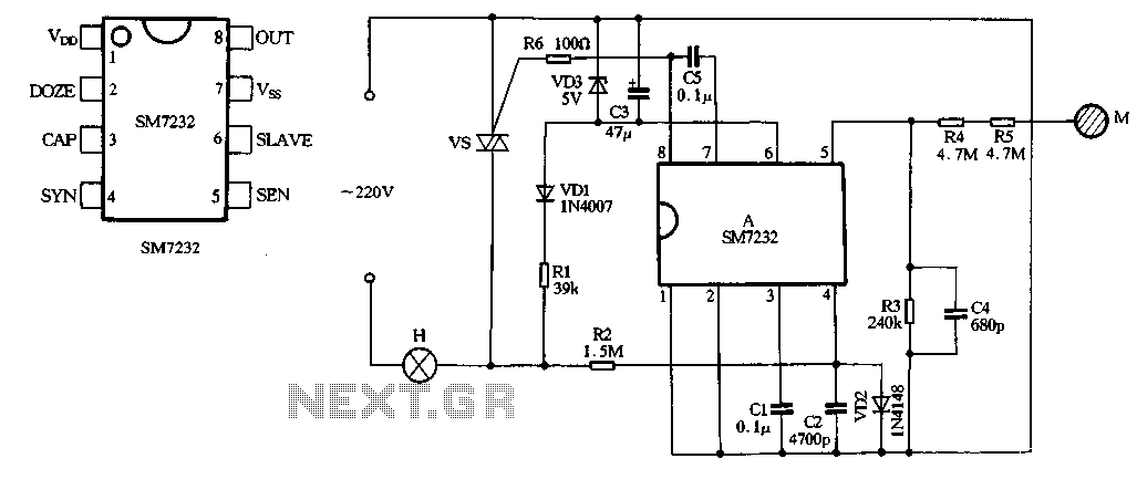
The core component of the circuit is the dimmer, utilizing the SM7232 integrated circuit. The pin configuration includes: 1) VDD, the positive power supply terminal; 2) DOZE; 3) CAP; 4) SYN, which synchronizes input power frequency using an internal...