
Heart Rate Monitor

The circuit operates on the principle of photoplethysmography, where the LDR detects variations in light intensity caused by changes in blood volume in the fingertip. The LDR's resistance decreases when illuminated, allowing current to flow, which is modulated by the pulsing of blood. The dual op-amp configuration amplifies this minute signal to a sufficient level for accurate measurement.
The choice of the LM358 or JFET L072 op-amp is critical due to their low power consumption and suitable bandwidth for this application. The gain settings, determined by the feedback resistors, ensure that even small fluctuations in light caused by blood flow can be translated into a measurable output. The use of capacitors serves to filter out high-frequency noise, ensuring that the output is stable and representative of the heart rate.
The output can be displayed on various types of analog meters, allowing for flexibility in design and user preference. The inclusion of a series resistor protects the meter from excess current, preventing damage during operation. This design's simplicity and effectiveness make it an excellent project for understanding basic electronic principles and the application of op-amps in signal amplification.
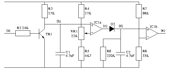
When using this circuit, it is crucial to maintain a steady position of the finger over the LDR to avoid inaccuracies in measurement. Environmental factors such as ambient light can also influence the readings, necessitating a controlled lighting condition for optimal performance. Overall, this circuit exemplifies how basic components can be utilized creatively to achieve complex functions, such as monitoring heart rate.Strictly speaking, this simple circuit shouldn`t work! How could anyone expect an ordinary light dependent resistor photo cell to `see` through a fingertip in natural daylight and detect the change in blood flow as the heart pulsates The secret is a high gain circuit, based on a dual op amp IC which can be either the low power LM358 or the JFET T L072. The LDR is connected in series across the 9V battery supply via a 100kO resistor (R1) and the minute signal caused by the blood pulsing under the skin is fed to the non-inverting (+) input, pin 3, of IC1a via a 0. µF capacitor. Pin 3 is biased by a high impedance voltage divider consisting of two 3. 3MO resistors. The feedback resistors to pin 2 set the gain to 11 times. The output of IC1a is fed via a 0. 47 µF capacitor and 220kO resistor to IC1b. This is configured as an inverting op amp with a gain of 45 so that the total circuit gain is about 500.
The output of IC1b is used to drive an analog meter which may be a multimeter set to the 10V DC range or any panel meter in series with a resistor to limit the current to less than its full-scale deflection. The prototype used an old VU meter with a 47kO resistor fitted in series. Note that the unit was designed to use the Dick Smith Electronics light dependent resistor (Z-4801). Other LDRs may require a change in the value of resistor R1. A light source such as a high brightness LED is not required. All that is needed is a reasonably well-lit room, preferably natural daylight, to produce a healthy swing of the needle.
Only when the hands are very cold does it make it a little more difficult to accurately count the pulses. To check your heart rate, carefully position your thumb or finger over the LDR and count the meter fluctuations for a period of 15 seconds.
Then multiply the result by four to obtain your pulse rate. The circuit can not be used if you are walking or running, etc. 🔗 External reference
Related Circuits
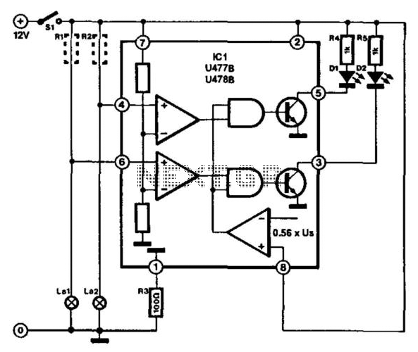
This circuit is designed for monitoring automotive lighting. Two specialized integrated circuits (ICs) from Telefunken are used to measure the current through a light bulb. Detecting whether current flows through a bulb is an effective method to determine its...

The circuit diagram illustrates a digital precision pressure tester using the MAX1457 integrated circuit with an external ROM selection of the 93C66 type, which is a 4096-bit E2PROM. Upon powering on, the MCS pin is pulled to a high...

The LM4844 is an integrated audio subsystem designed for stereo cell phone applications. Operating on a 3.3V supply, it combines a stereo speaker amplifier delivering 495mW per channel into an 8Ω load and a stereo OCL headphone amplifier delivering...

The ArduinoISP Bootloader/Programmer Combination Shield (not displayed) works with an Arduino equipped with a USB to serial chip (e.g., Arduino Uno) to upload the bootloader and sketches to a DIYduino. A USB to Serial programmer can also be utilized...

A simple and effective LED-based night lamp circuit is designed to operate directly from the 230V mains supply. The circuit utilizes a total of 24 white LEDs, producing an output of approximately 15W. Current limiting is achieved through resistor...
IC1 is a dual operational amplifier. In this circuit, each op-amp functions as a voltage comparator. When the voltage at the positive input exceeds the voltage at the negative input, the output transitions to a high state. Conversely, when...