
Heart Rate Sensor

The light reflectance sensor typically consists of a phototransistor, which is the primary component for detecting light levels. The schematic drawing illustrates the connections and layout of the circuit, emphasizing the importance of proper wiring to ensure accurate readings. The phototransistor, when exposed to light, generates a current that can be measured and interpreted by the connected heart sensor.
In the assembly process, careful removal of the phototransistor is crucial to maintain the integrity of the circuit. Once the phototransistor is detached, the three wires intended for connection to the heart sensor must be securely attached. The use of the existing leads from the phototransistor can simplify this process, allowing for a more straightforward connection without needing to solder directly onto the circuit board.
The schematic also indicates the placement of resistors and capacitors that may be present in the circuit, which can help stabilize the output signal and filter any noise that may interfere with the sensor's performance. Proper attention to these components will enhance the reliability of the light reflectance sensor in measuring light intensity, which is essential for accurate heart rate monitoring in various applications.Here is the inside of the light reflectance sensor (top) and a schematic drawing of it's circuitry (bottom). First, carefully remove the phototransistor as shown. Then, attach the three wires that we will connect to the heart sensor (show in bright yellow). Hint: if you leave the leads from the phototransistor when you cut it off, you can attach the two corresponding wires directly to them, rather than to the circuit board itself.
🔗 External reference
Related Circuits
A project involving a moisture sensor alarm circuit designed to detect moisture levels in plant soil, wood, and irrigation areas. The moisture sensor alarm circuit typically consists of a moisture sensor, a microcontroller or comparator circuit, an alarm system, and...
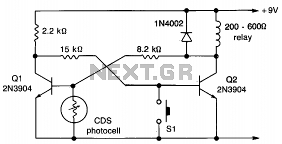
This circuit employs a flip-flop configuration utilizing Q1 and Q2. Under normal conditions, Q1 is heavily conducting. When light is detected by the CDS photocell, the bias on Q1 decreases, resulting in its cutoff, which activates Q2 and removes...
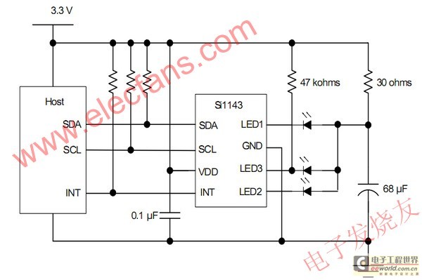
The electronic device detects proximity, measuring the user's distance quickly. Currently, most proximity sensors available on the market have a relatively short detection range of approximately 1 to 10 cm. The use of infrared LEDs in multipulse mode for...
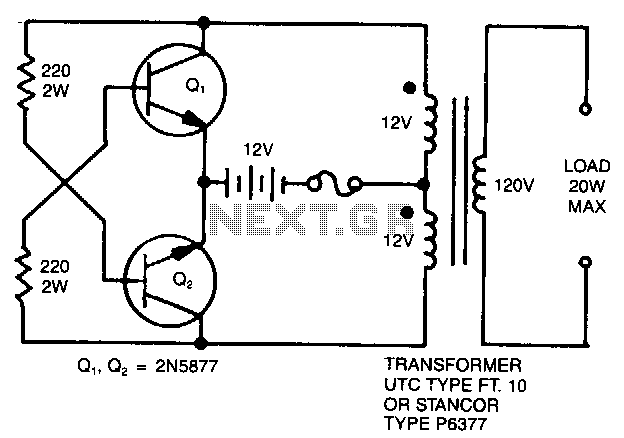
A simple 120 V to 24 V center-tapped control transformer, along with four additional components, can accomplish the task. This circuit produces a clean 200 V peak-to-peak square wave at 60 Hz and is capable of supplying up to...
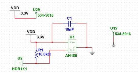
The chosen Hall Effect sensor is the AH180 Micropower Omnipolar Hall-Effect Sensor Switch. This sensor is utilized to detect the removal of a cup. The operational principle of the Hall Effect sensor involves outputting a high or low signal...
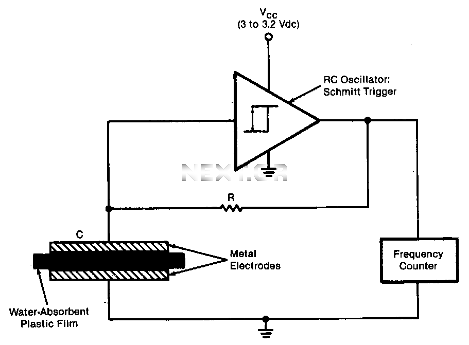
The sensor operates as an RC oscillator, utilizing a water-absorbent plastic film as the insulator within the capacitive element. The capacitance of this film increases with the amount of water it absorbs from the air, resulting in a reduction...