
Light-operated switch

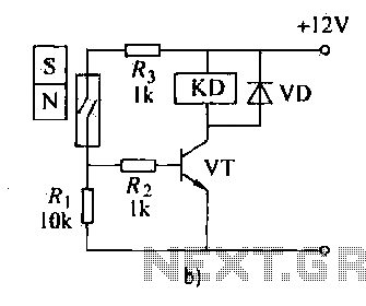
The circuit operates based on the interaction between two flip-flops, Q1 and Q2, which are typically configured as a bistable multivibrator. In this arrangement, Q1 remains in a conducting state under standard conditions, allowing current to flow through it. The CDS (Cadmium Sulfide) photocell serves as a light-sensitive resistor that influences the biasing of Q1. When ambient light levels increase, the resistance of the CDS photocell decreases, which leads to a reduction in the bias voltage applied to Q1.
As Q1's bias diminishes, it eventually reaches a threshold where it stops conducting, effectively turning it off. This action triggers Q2 to turn on, as it is designed to respond to the state change of Q1. With Q1 non-conducting, Q2 can now conduct fully, which further ensures that the bias on Q1 is removed, thereby reinforcing the state change.
The reset mechanism is an important feature of this circuit. By pressing switch S1, the circuit can be returned to its initial state, allowing Q1 to regain its conducting status. This reset functionality is crucial for applications that require periodic reinitialization of the circuit's state, ensuring reliable operation in varying light conditions.
Overall, this flip-flop circuit design is effective for applications that need to respond to light levels, providing a simple yet robust mechanism for switching based on environmental conditions.This circuit uses a flip-flop arrangement of Ql and Q2. Normally Ql is conducting heavily. Light on CDS photocell causes Ql bias to decrease, cutting it off, turning on Q2, removing the remaining bias from Q1. Reset is accomplished by depressing S1.
Related Circuits
The automatic weapon features a magnetic switch circuit that is simple, reliable, has a low failure rate, and offers good versatility. It can be used to output performance or convert mechanical displacement. The circuit diagram utilizes a Hall switch...
This weblog discusses electronic circuit schematics, PCB design, DIY kits, and electronic project diagrams. The circuit diagram presented is for a magnetic proximity switch, which has numerous applications across various fields. The circuit utilizes a magnetic reed switch (S1)...
This circuit is designed to double nearly any DC input voltage while handling a substantial amount of current. For instance, it can work with input voltages ranging from 12 to 24V. With minor modifications, it can also provide any...
An ultra-sensitive gauss meter circuit schematic serves as a simple indicator with no measurement, scaling, or accuracy. It consists of a Hall effect device or integrated circuit on a board with power supply inputs, minimal signal conditioning comprising approximately...

Transistors Q1 and Q2 control latches Q3 and Q4 to switch on the lamp. A high resistance from touching the electrode biases Q1 or Q2 on, setting or resetting the latch. In this circuit, transistors Q1 and Q2 function as...
This circuit functions with inaudible (ultrasonic) sound. Sound of frequency up to 20 kHz is audible to human beings. The sound of frequency above 20 kHz is called ultrasonic sound. The circuit described generates (transmits) ultrasonic sound of frequency...