
Heating System Thermostat

The circuit operates by utilizing two temperature sensors: one external sensor monitors the outdoor temperature, while the second sensor, located on the return water pipe, detects the temperature of the water coming back from the heating system. This dual-sensor approach ensures that the heating system can effectively respond to changes in both indoor and outdoor temperatures.
The external temperature sensor can be a thermistor or a thermocouple, which provides an analog voltage proportional to the ambient temperature. This signal is fed into a microcontroller or comparator circuit that processes the temperature data. The indoor temperature sensor, similarly, monitors the internal environment, ensuring that the heating system maintains a comfortable temperature regardless of external conditions.
The control logic is designed to compare the readings from both sensors. When the indoor temperature falls below a predefined threshold, the control system activates a relay, which is wired to the boiler's start-stop control input. The relay acts as a switch, allowing the boiler to turn on and heat the water circulating through the system. Conversely, when the desired indoor temperature is reached, the relay opens, cutting off the boiler's operation.
The simplicity of the design contributes to its high reliability. The components used in the circuit are chosen for durability and longevity, ensuring that the system remains operational over extended periods. The circuit's effectiveness has been validated through years of use in residential settings, demonstrating its capability to maintain stable indoor temperatures efficiently.
In summary, this heating control circuit exemplifies a straightforward yet effective solution for temperature regulation, leveraging basic components to achieve consistent performance and reliability over time. Proper installation and calibration of the sensors are crucial for optimal operation, ensuring that the heating system responds appropriately to both indoor and outdoor temperature fluctuations.This circuit is intended to control a heating system or central heating plan, keeping constant indoor temperature in spite of wide range changes in the outdoor one. Two sensors are needed: one placed outdoors, in order to sense the external temperature; the other placed on the water-pipe returning from heating system circuit, short before its input to the boiler.
The Relay contact wiring must be connected to the boiler`s start-stop control input.Controlled by indoor and outdoor temperature Simple, high reliability design. This circuit, though simple, has proven very reliable: in fact it was installed over 20 years ago at my parents` home. I know, it is a bit old: but it is still doing its job very well and without problems of any kind. When Q1 Base to ground voltage i 🔗 External reference
Related Circuits
Application note on designing linear and switch-mode (switching DC-DC converter current source) battery charger applications that require external microcontrollers and related system-level issues for notebook computers. The application note provides guidance on the design of both linear and switching DC-DC...
1990 Acura Integra Starting System Wiring Diagram. The 1990 Acura Integra starting system wiring diagram provides a visual representation of the electrical connections and components involved in the vehicle's starting system. This diagram is essential for understanding the layout and...

Combine an electrostatic transducer with an ultrasonic transceiver integrated circuit (IC) to create a ranging system capable of sensing objects at distances from 4 inches to over 30 feet. The broadband characteristics of transducer Y1 simplify the tuning process....
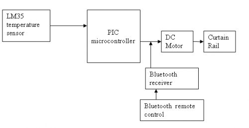
The circuit is designed for a DC motor and Bluetooth system, where the Bluetooth remote control is utilized to open and close curtains. A block diagram is provided for reference. A mobile phone can be used to develop a...
A four-channel data telemetry system featuring electronic circuits, schematics, hobby kits, custom electronics design, and a tutorials homepage. This platform offers a wealth of free, functional electronic circuits and a discussion forum with thousands of members to engage in...
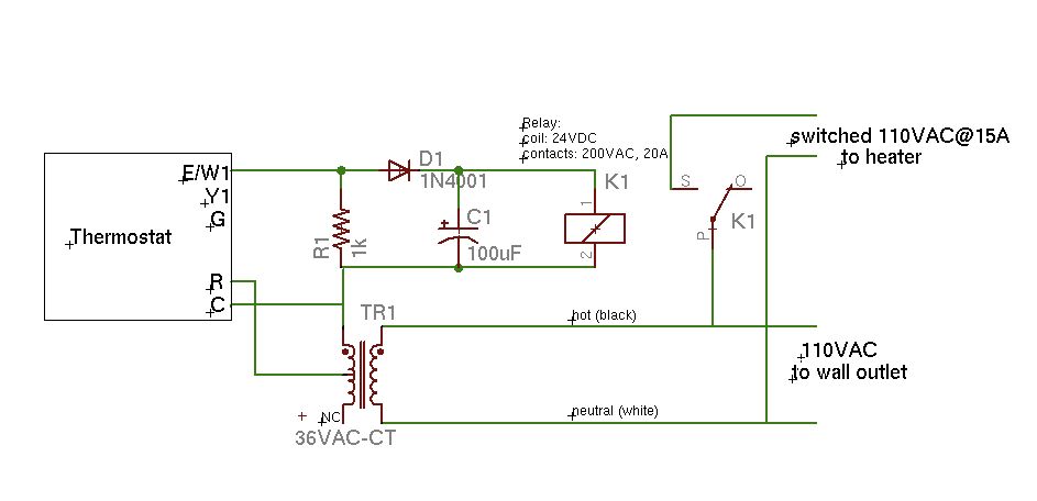
A basic schematic of the circuit is presented, marking the initial experience with Eagle software. It is important to note that only the W1 output of the thermostat is utilized, while C serves as the common connection. The schematic outlines...