
Help with Laser Alarm Circuit

The Laser Alarm System is a security device that utilizes laser beams to detect unauthorized entry or movement within a designated area. The fundamental operation of this system involves a laser source, a photodetector, and a microcontroller or alarm module.
The laser source, typically a laser diode, emits a focused beam of light across the area to be monitored. This beam is directed toward a photodetector, which can be a photodiode or a phototransistor. When an intruder or an object interrupts the laser beam, the photodetector senses the absence of light and triggers an alert.
The microcontroller or alarm module processes the signal from the photodetector. Upon detecting a break in the laser beam, the microcontroller can activate an alarm, send a notification, or execute other programmed responses. The system may include additional features such as adjustable sensitivity, delay timers to prevent false alarms, and integration with other security systems.
Power supply considerations are crucial in the design of a Laser Alarm System. The laser diode typically requires a specific voltage and current, which must be supplied through a regulated power source. Similarly, the photodetector and microcontroller will have their own power requirements that need to be met.
In terms of circuit design, the layout should minimize interference and ensure that the laser beam is properly aligned with the photodetector. Proper shielding may be necessary to protect sensitive components from environmental factors.
Overall, the Laser Alarm System is an effective and versatile project for those interested in electronics, providing hands-on experience with optical sensors, microcontrollers, and alarm systems.Hey all I`m new to both the forums and electronics. Recently I chanced upon a Laser Alarm System and decided to give it a go.. 🔗 External reference
Related Circuits
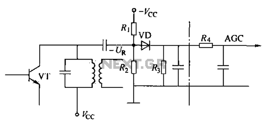
Commonly referred to as an automatic gain control (AGC) circuit, it is primarily utilized in receivers. This circuit maintains a constant output voltage amplitude despite variations in the input signal amplitude. It ensures that the receiver can effectively process...
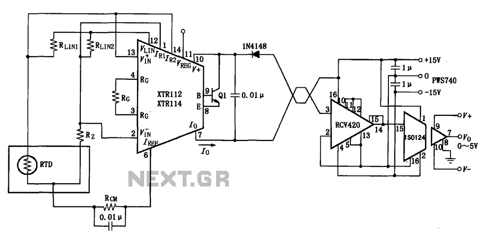
The RTD temperature data collected at the scene is converted into a voltage using the XTR112/114. This voltage is further transformed into a 4 to 20 mA current output, which is then transmitted via a twisted pair. The RCV420...
This circuit can be constructed using readily available low-cost components, some of which may be found in a junkbox. The specified value of 22 ohms for resistor R1 results in an average current of approximately 65 mA through the...

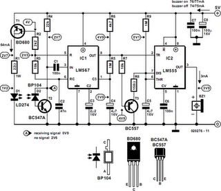
FIG IC, ICR, Ri, R, and AN composition form a bistable contact circuit with a Ge transistor. It includes components such as ICc, lc, c2, and Dj, and is associated with a one-shot delay circuit. The circuit can be...
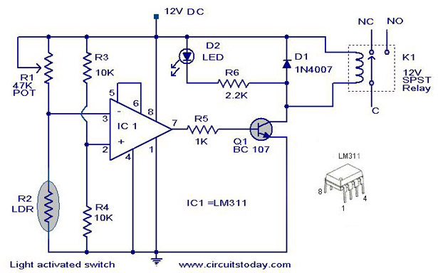
A simple light-activated switch circuit diagram utilizes the National Semiconductor comparator IC LM311 and a light-dependent resistor (LDR). The circuit functions as a voltage comparator, with the non-inverting input of IC1 receiving a reference voltage of 6V through resistors...
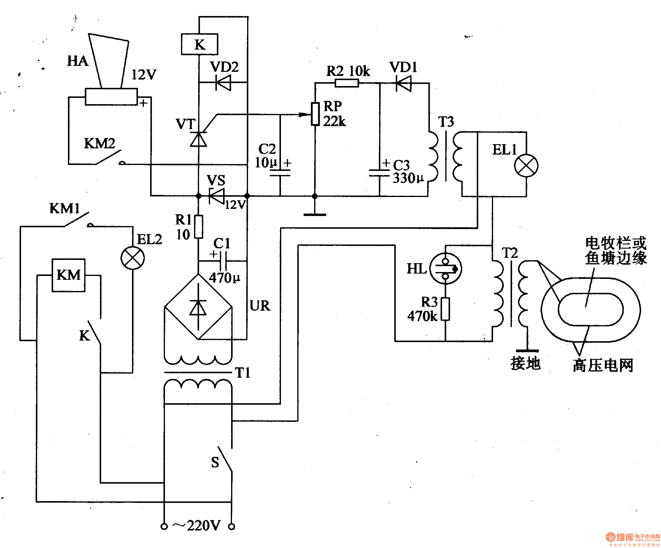
The electric fence control circuit consists of three main components: the power supply circuit, the high voltage circuit, and the sound and light alarm circuit, as illustrated in Figure 4-26. The power supply circuit includes a power switch (S),...