
hi-fi Loudspeakers plans

I copied the Linkwitz circuit from an article in the November 1990 Elektor Electronics magazine. It was entitled "Active Mini Subwoofer, part 1," written by T. Giffard. I suggest you try to obtain a copy of that article. It gives all the necessary equations to calculate proper component values for the Linkwitz circuit, for your specific box and driver.
Now let's go on to the crossover: Again, this is not my own design, but is taken from "Active Phase-linear Crossover Network," published by Elektor Electronics in September 1987. It mentions Stanley Lipshitz and John Vanderkooy as designers of this circuit. I just changed component values but kept all of the basic design.
U2A and B form a fourth-order low pass filter with a cutoff frequency somewhat below 500 Hz. U3A and B are used as an all-pass filter (no frequency limiting action), that has exactly the same delay characteristics as the low pass filter, plus an 180-degree phase reversion. Thus, at pins 7 of U2 and U3 respectively, the signals are exactly phase-opposed, and U2 is delivering only the low range, while U3 is still delivering the entire range.
U3C and D make up another fourth-order low pass filter, but this one cuts off somewhat below 5 kHz. And there are two all-pass filters with the same delay as this low pass one: U2C and D, and U4A and B. So, at U20 pin 14 we have the low range, which is directly applied to the woofer level potentiometer. At U3 pin 14 we have the low and medium ranges, in the same phase. Applying these two signals to a differential amplifier (U4D), we keep the medium range and suppress the low range. This signal is applied to the squeaker level pot. Lastly, at U4 pin 7 we have the entire audio range, in opposite phase to the bass-plus-medium-ranges signal at U3 pin 14. Simply adding the two signals together produces an output of only the high range, which is applied to the tweeter level pot. As a bonus, the three output signals are in the same phase.
The circuit design employs a subtractive crossover architecture, which utilizes fourth-order filters to achieve a steep separation of individual speaker responses while maintaining a flat overall frequency response. This is advantageous when dealing with multiple speakers, as it allows for better integration of the sound produced by each driver. The use of high-order filters minimizes the potential for interference between speakers, particularly in frequency ranges where two drivers may respond simultaneously.
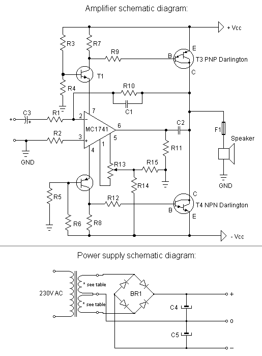
The amplifiers are designed using operational amplifiers configured as drivers, which pass their supply current through the base-emitter junctions of two power transistors. This configuration allows for local and overall feedback loops, which must be carefully balanced to ensure stability. Resistors in parallel with the transistor base-emitter junctions set the idling current of the transistors, which is crucial for maintaining consistent performance and minimizing distortion. The selected idling current of approximately 100 mA ensures that the transistors operate in a class-A mode, preventing crossover distortion and achieving a clean signal output.
The output stage of the amplifiers is capable of delivering around 12 W into 8 Ohm speakers. The design emphasizes simplicity while providing high fidelity, ensuring minimal distortion and high-quality audio reproduction.
A relay circuit is included to manage speaker connections, featuring a timer that delays the activation of the speakers by about one second. This delay allows the circuit to stabilize before the speakers are engaged, thereby preventing audible clicks or pops when powering on or off. The relay's function is critical for protecting the speakers and enhancing the overall user experience, although it may be omitted if cost savings are prioritized.The entire circuit is powered from a very simple regulated +-15V power supply, that is able to deliver about 2 A continuous duty, and at least 6 A on musical peaks. Two three-terminal regulators with power transistors wrapped around them do the regulating job. Here in chile we have a 220 V power grid, but of course feel free to use a transformer with a primary suited for your local voltage.
The audio signal enters at U1A, which is a simple voltage follower, delivering the signal to U1B. This operational amplifier is wired as a Linkwitz resonance compensation filter. It has a frequency response that is the exact opposite of the low-end woofer response, thus expanding the low bass coverage into frequencies that fall below the natural resonance, and would be strongly suppressed without the filter. Note that some components are specified at rather strange values. These are the exact values computed to compensate the specific behavior of my woofers in my cabinets. If you don't use the exact same speaker, and the exact same materials and dimensions for the cabinet, you will need to recalculate these values.
I used the standard values that come closest to the ones stated here, but again, don't copy this part of the circuit blindly, because it will NOT work properly if your woofer or cabinet are different from mine. I copied the Linkwitz circuit from an article in the november 1990 Elektor Electronics magazine. It was entitled "Active Mini Subwoofer, part 1", written bt T.Giffard. I suggest you try to obtain a copy of that article. It gives all the necessary equations to calculate proper component values for the Linkwitz circuit, for your specific box and driver.
Now let's go on to the cross-over: Again this is not my own design, but is taken from "Active Phase-linear Cross-over Network" , published by Elektor Electronics in September 1987. It mentions Stanley Lipshitz and John Vanderkooy as designers of this circuit. I just changed component values, but kept all of the basic design. U2A and B form a fourth-order low pass filter with a cutoff frequency somewhat below 500 Hz. U3A and B are used as an all-pass filter (no frequency limiting action), that has exactly the same delay characteristics as the low pass filter, plus an 180 degree phase reversion.
Thus, at pins 7 of U2 and U3 respectively, the signals are exactly phase-opposed, and U2 is delivering only the low range, while U3 is still delivering the entire range. U3C and D make up another fourth-order low pass filter, but this one cuts off somewhat below 5 kHz. And there are two all-pass filters with the same delay as this low pass one: U2C and D, and U4A and B.
So, at U20 pin 14 we have the low range, which is directly applied to the woofer level potentiometer. At U3 pin 14 we have the low and medium ranges, in the same phase. Applying these two signals to a differential amplifier (U4D), we keep the medium range and suppress the low range.
This signal is applied to the squeaker level pot. Lastly, at U4 pin 7 we have the entire audio range, in opposite phase to the bass-plus-medium-ranges signal at U3 pin 14. Simply adding the two signals together produces an output of only the high range, which is applied to the tweeter level pot.
As a bonus, the three output signals are in the same phase. Beautiful, isn't it? You could ask why I used this circuit, instead of a simpler low-pass, band-pass, high-pass approach. After all, the exact phase relationship anyway gets destroyed by the three speakers. Well, the phase linearity of this circuit is just a by-product, not the main thing. The real reason for using this approach is this: If you use three separate filters, it is nearly impossible to match them so well that the composite frequency response remains flat. Even if you do a very careful design, and use parallel combinations of components to get precise values, you still have to calibrate each individual circuit, simply because of inevitable component tolerances.
If you use first order filtering, like in most passive crossover circuits, this problem is not too serious, but it becomes unmanageable for high order filtering. Now, why would you want high order filters at all? Simply because this minimizes the problem of a single signal coming from two separated sources, for signals that fall in the range where TWO speakers respond to it.
So, using the subtractive crossover, we can use fourth-order filters, with the resulting steep separation of individual speaker responses, and keeping the overall response very flat. If a low-pass filter cuts off a little higher or lower, simply the other speaker will fill in the missing sound, or make room for the other's response.
If you build two speaker systems, with three amplifiers in each, that makes six of them. So, it pays to look for a design that provides good performance, while being extremely simple. The circuit used in this project is a standard application mentioned in many op amp data sheets. An op amp is used as a driver, passing its supply current through the base-emitter junctions of two power transistors. There is a local feedback loop and an overall feedback loop, and the gain of these two loops has to be carefully balanced in order to get stability.
Resistors in parallel to the transistor base-emitter junctions shunt a part of the op amp's current, thus setting the idling current of the transistors at a safe value. In this circuit, the idling current was chosen at around 100 mA, which gives 3 W of static power dissipation in the transistors.
This is low enough to be easy to handle from the thermal point of view, while at the same time it is high enough to guarantee that the transistors never switch off, thus giving true expanded class-A operation, and eliminating cross-over distortion. These amplifiers can deliver approximately 12 W each into 8 Ohm speakers, and despite my efforts, I could never measure or hear any distortion coming from them.
They are extremely clean, despite their almost ridiculous simplicity! The only part of the schematic now remaining to comment is the circuit around the relay. This is just a timer, that delays the speaker connection by about one second, so they come in when the entire circuit has had time to settle down. When the power is switched off, the relay shuts the speakers off almost immediately, before the amplifiers' DC levels can destabilize.
So, the timer completely eliminates clicking or popping in the speakers when switching the active speakers on or off. It has no other function, so if you want to save the cost of the relay, you can do so, at the expense of some slight popping...
🔗 External reference
Related Circuits
A tone control circuit is an electronic circuit designed to manipulate the tone of an audio signal. The tone of an audio signal is analogous to color in light. The tone control circuit typically consists of various components such as...
The sound system features a de-sensitized design with a maximum range that can be increased if desired. It includes two tone controls: one offering a lift of 10 dB and the other providing a subtle cut of 3 dB....
A modification to David Knight's linear detector circuit was developed to create a high-fidelity AM receiver requiring an ultra-linear AM detector. The revised circuit eliminates the meter circuit and many bypass capacitors, resulting in a design with a finite...
Detailed plans to build devices for HHO, HOH, HOD, PWM pulse width modulators, and EFIE electronic fuel injection enhancers. The schematic for constructing devices related to HHO (Hydrogen-Hydrogen-Oxygen) production, HOH (Water), HOD (Hydrogen-Oxygen-Diatomic), PWM (Pulse Width Modulation) controllers, and EFIE...
This is a straightforward, cost-effective Hi-Fi quality power amplifier. It can be constructed in five different configurations, as indicated in the table, ranging from 20 W to 80 W RMS. This Hi-Fi quality power amplifier is designed to deliver high...
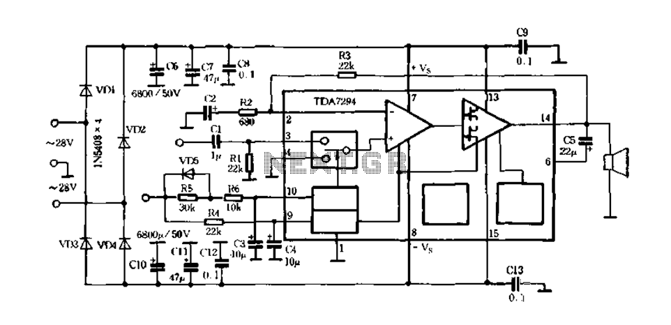
Europe's leading SGS-THOMSON STMicroelectronics recently introduced a new hydrazine fos power integrated amplifier, the TDA7294, to the Chinese mainland. This amplifier has surpassed traditional linear integrated amplifiers and has been successfully released for Hi-Fi applications, such as home theaters...