
Motorola Hi-Fi power amplifier

This Hi-Fi quality power amplifier is designed to deliver high audio fidelity while maintaining affordability. The amplifier's versatility allows for five distinct configurations, enabling users to select the appropriate power output based on their specific requirements. The output power options range from 20 W to 80 W RMS, accommodating various speaker systems and listening environments.
The circuit typically comprises a differential input stage, which enhances common-mode rejection and improves overall sound quality. Following this, a voltage amplification stage boosts the signal before it reaches the output stage, which is responsible for driving the load. The output stage may utilize transistors or integrated circuits, depending on the selected configuration, to achieve the desired power output.
To ensure optimal performance, the amplifier includes various feedback mechanisms that stabilize the gain and reduce distortion. Additionally, power supply considerations are crucial; a well-regulated power supply with appropriate filtering will significantly influence the amplifier's performance and noise levels.
Thermal management is also an important aspect of the design, as power amplifiers can generate substantial heat during operation. Adequate heat sinking and ventilation must be incorporated to prevent overheating and ensure reliable operation over extended periods.
Overall, this power amplifier design offers flexibility, efficiency, and high-quality audio reproduction, making it suitable for a wide range of audio applications.This is a very simple, low cost, Hi-Fi quality power amplifier. You can build it 5 ways, like its shown in the table (from 20 W to 80 W RMS).. 🔗 External reference
Related Circuits
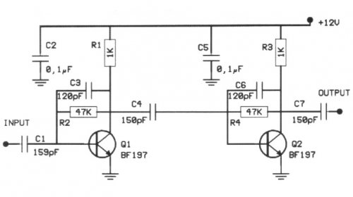
The following circuit illustrates a 20 dB VHF amplifier circuit diagram utilizing the BF197 transistor. Features include a simple circuit design. The 20 dB VHF amplifier circuit is designed to amplify very high frequency signals, making it suitable for applications...
This is a component of a 100W RF amplifier. This circuit is constructed using the RF power transistor BLY94. Components include the BLY94 transistor, inductor, and others. The 100W RF amplifier circuit utilizing the BLY94 transistor is designed to amplify...
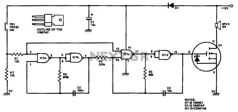
ICla and IClb are configured as a slow astable multivibrator, while IClc and ICld are arranged as a fast astable multivibrator. The output from the slow astable modulates the frequency of the fast astable, and the output from the...
This power supply circuit is highly stabilized that its output voltage will drop only 0.005% even though the load changes from 0 to 100%. Another excellent capability is that the output voltage will change only by 0.01% if the...
The incoming AC is routed to the primary terminals of a 12.6-volt transformer. The hot side of the AC is connected through a fuse and a single-pole single-throw (SPST) toggle switch. When the switch is in the OFF position,...

A very high-power amplifier with 10 pairs of power transistors. It can utilize MJ15024 and MJ15025 or MJ21193 and MJ21194. These 20 transistors function as the final active components. The design is based on four integrated circuits: TL072, TL074,...