
High and low frequency signal generator circuit diagram

The high-frequency signal generator circuit operates by utilizing a combination of transistors, capacitors, and inductors to create oscillations at specified frequencies. The transistors (VT1 to VT3) serve as the main amplification elements, allowing for the generation of the desired frequency signals. The choice of transistors such as the 3DGl00 or 3DG201 ensures that the circuit can operate efficiently at high frequencies while maintaining low power consumption.
The capacitors play a critical role in determining the frequency response of the circuit. C7, with its dual configuration options, allows for fine-tuning of the oscillation frequency. The oscillation transformer, constructed with L1 and L2, is essential for coupling the generated signal and ensuring stability in the oscillation process. The specified number of turns in the inductors (100 for L1 and 35 for L2) is crucial for achieving the desired inductance values, which directly influence the frequency characteristics of the circuit.
Capacitor C8, being a mica capacitor, is chosen for its stability and low loss characteristics, which are important for maintaining signal integrity at high frequencies. The inclusion of three-stage ceramic filters for the 465 kHz IF signal enhances the selectivity and minimizes interference from unwanted signals, ensuring that the output is clean and usable for radio applications.
The optional DPDT switch (S1) provides versatility in circuit operation, allowing users to toggle between different modes or outputs as needed. This feature is particularly beneficial for experimentation and debugging purposes, enabling users to assess the performance of various configurations without the need for extensive rewiring. Overall, this high-frequency signal generator is an invaluable tool for both novice and experienced electronics enthusiasts, facilitating the exploration and repair of radio frequency circuits. As shown in the high-frequency signal generator capable of generating a low frequency 1kHz, 465kHz IF signal and the high frequency of 525 ~ 1605kHz, to repair radios or other circuit debugging very helpful for beginners production. Transistor VTl ~ VT3: choice 3DGl00,3DG201 other high-frequency low-power silicon tube, fT 100MHz, values between 50 and 100. C7 can be used 7/270pF radio with double or single row of capacitors connected capacitors. Oscillation transformer T can be carried out in radio in the week on the restructuring, on the core with a high strength wire 0.08mm around Ll, 100 turns, L2,35 turns.
C8 510pF available mica capacitors. Q three-stage selection of 465kHz IF ceramic filters. Sl optional DPDT type switch. Other component values shown in Figure labels.
Related Circuits
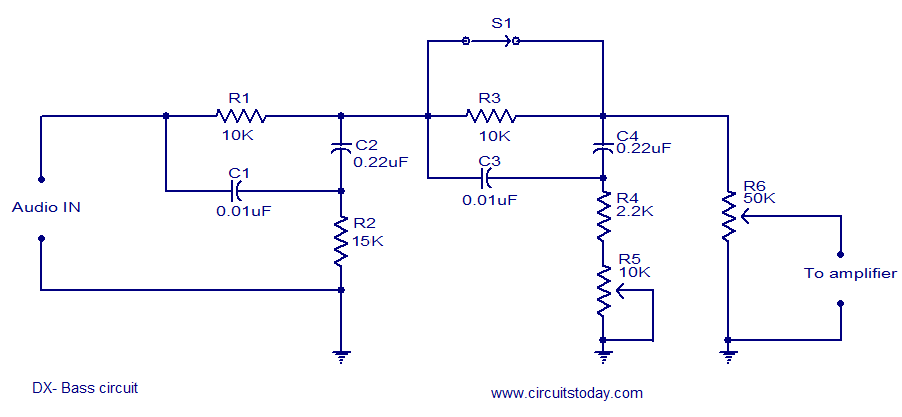
The circuit diagram of a passive DX bass circuit is presented, which is compatible with nearly all audio amplifiers. This design was created by Mr. Emmanuel Chipula from Malawi and submitted for publication. Laboratory tests confirmed satisfactory performance. Credit...
Electrical signals travel along the neurons in the brain and body, continuously transmitting information throughout the complex system. Without these signals, the body would function like a plant, with different parts unaware of each other's conditions, making animal life...
This circuit is a difference amplifier. It functions as an inverting amplifier that enables the subtraction of two voltages, effectively performing a summation. The difference amplifier is a fundamental circuit configuration in analog electronics, primarily used for amplifying the difference...
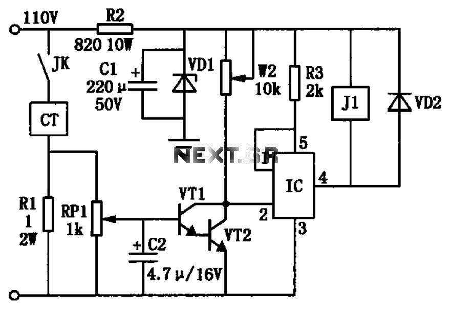
The circuit depicted in the figure utilizes a +24V power supply derived from a 110V power source through an electromagnetic chuck. When the electromagnetic chuck circuit is activated, the contact JK closes, enabling the operation of the magnetic chuck....
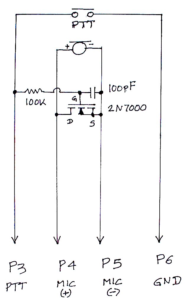
The TS-440S, similar to several other radios, does not mute the microphone when utilizing the rear audio connector for digital modes. Consequently, unless the microphone is unplugged each time digital modes are used, background noise from the shack can...
R1, D3, and C1 are optional components. Only one LED is necessary. If the LED does not illuminate, try reversing its polarity. Initially, a single 555 circuit was used, but high current consumption was a concern. Additionally, the R5...