
Key Code Combination High Security Door Lock


Specifications:
- Power supply: 9 VDC, powered by a 9V battery
- Current consumption: 0.1 mA at rest, 40 mA when the relay is activated
Possibilities:
- Thousands of four-digit combinations
- Operates only with the correct number sequence
- Option to use misleading numbers for resetting
- Compatible with alarm circuits
- LED indicator for correct combinations
- Device control via a built-in relay
- Low power consumption
- Integrated touch keyboard
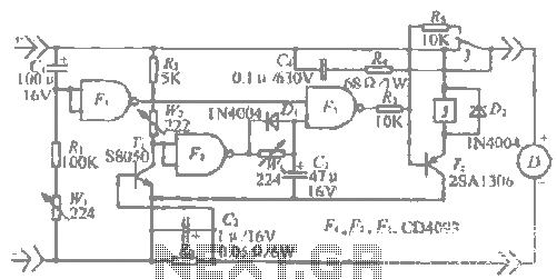
Function of the circuit: The simplicity of this construction is attributed to the use of integrated circuits. The design requires only a few external resistors, capacitors, a transistor, and a relay, allowing it to provide features typically found in more expensive locks. The core of the electronic lock consists of two CMOS 4013 integrated circuits, each containing two D flip-flops. The flip-flop's primary function is to change its output state when it receives a pulse or voltage at its input.
The system utilizes four distinct touch switches labeled "A," "B," "C," and "D." When one of these switches is activated, it connects the positive terminal of the 9VDC power source through resistors R1, R3, R7, and R9 to the clock inputs of the corresponding flip-flops. Activating the first switch ("A") sends a voltage to the clock terminal of the first flip-flop, changing its Q output state and triggering the second flip-flop. This process continues sequentially until the fourth flip-flop is activated, which subsequently energizes the relay via transistor Q1 and illuminates LED D2, indicating that the correct combination has been entered.
To enhance security, five additional circuit breakers are integrated in parallel with the reset key. These switches correspond to the four actual code numbers and can cancel the activation sequence of the flip-flops if any of these switches are inadvertently pressed. For instance, if the code is set to "6, 8, 4, 3," the relay will only activate when these exact numbers are pressed in the correct order. If a reset switch corresponding to a misleading number (e.g., 1, 2, 5, 7, 9) is pressed during the sequence, the circuit resets, requiring the user to start over.
Capacitors C1 and C2 are included to filter the supply voltage, eliminating unwanted noise and interference.
The D Flip-Flop: This component is a bistable circuit that can switch between two states based on a control signal at the input, maintaining its state until the next input pulse is received. The D flip-flop is characterized by its ability to store a value based on the previous input, hence the term 'delay' flip-flop.
Construction: The assembly process begins with a low-power soldering iron (15-25W). The first step involves attaching the relay outputs and the two integrated circuit boards (U1 and U2) with the notches facing upwards. The resistors (R1-R11) and capacitors (C1 and C2) are then soldered in place, ensuring correct polarity. Care should be taken not to overheat sensitive components such as diodes D1 and D2, which are connected in series with their cathodes at unmarked points.
To set the secret code, connections must be made from points A, B, C, and D to the corresponding rows on the board, following the designated sequence. Misleading numbers can also be connected to enhance security against unauthorized access attempts. The integrated circuits should be installed carefully to avoid damage from static electricity.
After assembly, the circuit should be powered with a 9V battery, which is designed for low consumption and can last several months. Testing the functionality involves entering the designated four-digit code; upon successful entry, the relay should activate, confirming that the circuit is operational. If issues arise, troubleshooting should focus on checking for short circuits, cold solder joints, and correct component orientation.
Components:
- R1, R3, R5, R7, R9: 100KΩ, 1/4W
- R2, R4, R6, R8, R10: 4.7MΩ, 1/4W
- R11: 18KΩ, 1/4W
- C1: 100nF Polyester
- C2: 220μF/16V electrolytic
- D1: 1N4148 universal diode
- D2: LED
- Q1: BC558 PNP transistor
- Relay: 6V relay
- U1, U2: CD4013 double D flip-flops
- 2 bases for CD4013
- 1 9V battery clipThis project is an electronic lock with many combinations that you can easily change and opens only with the correct combination of four consecutive numbers. The big advantage of the electronic lock is that the four numbers must be entered in the correct order one after the other.
If a number is wrong then the circuit automatically resets to its resting state and the combination of the 4 numbers must go from the beginning. This is important when one tries to find the combination by doing tests, because the circuit will discourage him because he will return to calm for every wrong number.
Specifications
- Power supply: 9 VDC only with 9V battery
- Current: 0.1mA at rest 40 kA when the relay is closed
Possibilities
- Thousands of combinations of four-digit numbers
- Operate only with the correct number and the correct order
- Ability to use deceptive numbers for reset
- Collaboration with alarm circuits
- LED with LED when the combination is correct
- Device control via built-in relay
- Low power consumption
- Built-in touch keyboard
Function of the circuit
Due to the use of integrated circuits, the entire construction becomes simple. With only a few external resistors, capacitors, a transistor and a relay, this electronic lock offers all of the above-mentioned features and only encountered in much more expensive locks.
The heart of the electronic lock is the two integrated CMOS 4013 circuits that have two D FLIP-FLOPs each. The FLIP-FLOP function is pretty much known to the electronics. The basic property that we take advantage of in the circuit is that when a FLIP-FLOP receives a pulse or voltage at its input, it changes its output state.
Beginning with the touch switches, we notice that there are 4 separate switches with "A", "B", "C" and "D".
These switches, when closed, connect the (+) of the power source (9VDC) via the resistors R1, R3, R7 and R9 corresponding to the clock inputs of the four flipflop. When one of these switches is closed then the corresponding (F-F) changes state to its output (Q).
Starting from the first (F-F) and closing the switch (key "A") (the switch with the number to be pressed first), a voltage is displayed on the clock terminal of the first (F-F).
Automatically changes the Q output of (F-F) and feeds the second (F-F).
Then the second (F-F) stays in this state waiting to change its status. This will only be done after the second switch is pressed (key "B"). This will change the status of the second (F-F) and from the output (Q2) the pulse will pass to the 3rd (F-F) (Data input). The third (FF) remains in this state until the number (key "C") is changed to change the status of the third one (FF) to feed the Data 2 input of the fourth (FF) and finally the fourth number Key "D"), so that a voltage will be output at the pin 13 at QF of the fourth (FF) and will feed through the R11 transistor Q1 and then close the relay while the LED D2 will also light up indicating that the The entire placement procedure of the code number was given in the correct order.
In this simple way we can give key C and D switches any number we want by putting our own code number.
To make life difficult for anyone who wants the test method to break the lock by testing all possible numbers there are five circuit breakers connected in the circuit parallel to the reset key.
These switches are inserted in the order of 4 real codes and have the property of canceling the whole process of sequential 4 (F-F) activation if one of these switches is accidentally pressed.
That is, if we have given the keys "A" - "D" for example the numbers (6,8,4,3) the relay will only be closed if the number switches (6,8,4,3) And only then. By connecting one or more switches from the series of reset keys to the other numbers from the code that we put them ie 1,2,5,7,9 by pressing code 6,8 after the fifth immediately the circuit will automatically reset will come back Ie in the resting state, and the positioning of the code number 6,8,4,3 should be placed from the beginning in the correct order without another number being inserted.
This is so if someone who does not know the code attempts to open the lock by trying several four digits to be disappointed quickly after the circuit cancels the number each time it has set a number of the reset keys.
Finally, capacitors C2 and C1 filter the supply voltage from unwanted buzz and frequencies.
The D FLIP-FLOP
It is a circuit that has two constant states and has the ability to jump from one situation to another when a control signal is applied at the input and remains in this state after the control signal has been applied. So the flip flop can be considered as an elementary memory. D flip flop is a form (F-F) where the letter D defines the Delay word. This means that n output of the DFF is a function of the input that a pulse occurred earlier.
For example, if the logic "1" appears in the input after the next pulse, it will be 1.
The DFF changes its state after a pulse, ie when the control pulse is applied to the input, it will not immediately change state to Next input pulse. From this property he was called D (delay) flip-flop.
Construction
Use a low power (15-25W) solder earthed.
Start building by first attaching the legs to numbers 1 (+) 2 (-) 3,4 and 5 (relay outputs). Then attach the 2 U1 and U2 integrated circuit boards with the notches upward as shown on the board. Then glue the eleven resistors R1-R11, capacitors C1 and C2 (observe its polarity).
Finally, do not overheat the D1 and D2 diodes and observe their polarity by following the circuit board layouts. The diodes D1 and D2 are connected in series. The cathodes of both diodes are points that are not marked.
In Led (D2), the cathode is the notch with the notch while the foot with the coarse line is the cathode of D1.
After attaching all the components correctly, glue the 9V battery clips to the points 1 and 2 with the black cable at the (-) point 2 and the red at the (+) point 1.
Now you can place the secret number you only know. Suppose you want to enter code 4253. You will carefully follow the links below. Connect with a piece of wire in turn
- point A with the fourth row of holes
- point B with the second row of holes
- point C with the fifth row of holes
- point D with the third row of holes
This is how the 4253 code is placed
If you want to place the misleading numbers from one to five, make the following links:
Below points A, B, C and D there are 5 holes called reset.
Attach these five points to the five holes with the remaining rows of holes NOT connected, ie with the numbers 1 (first row) 6 (sixth) 7 (seventh) 8 (eighth) and 9 (ninth) series.
We advise you to place all five misleading numbers because it makes it harder for anyone to try to break the lock by trying different numbers.
Even if it knows that the code is four-digit, the probability of clicking a number of the reset keys is great and so the process is canceled. In this way he is quickly disappointed because the chances of finding the right code are minimal. Finally, place the integrated circuits on their bases taking care not to grasp them too much (it is best not to grab them with bare hands because it is CMOS but if you catch it, be sure to get rid of static loads first by grasping a grounding point such as a water pipe.
Their notches look upward as the printed circuit shows. Turn the board toward the side of the welds. Only supply the circuit with a 9V battery and not a power supply. Consumption is minimal. A 9V battery lasts many months.
Tap a random four-digit number. You will see that nothing will happen. Now tap the number you have selected. In this case, if the code is the number of the example, ie 4253, you will see that by first pressing 4 second 2, third 5 and 4, you will immediately hear the relay close and the LED will light up.
This shows that the circuit works. Try the number 4,2,8,5. He will not accept the circuit since the first two numbers 4 and 2 are correct but the third number (8) will reset and cancel the process.
If it does not work try to wet your fingertips.
If the circuit does not work
If the circuit does not work then check the following points carefully:
- Maybe you have shorted some point on the board mainly the feet of the integrated.
- You may have made cold soldering or have used excessive solderin.
- Perhaps you have placed a component upside down or someone else's position.
- You may have been overheating a sensitive component (diode, transistor or static IC loads because it is a CMOS.
- You may have mistaken the code and you have stuck two numbers on the same line.
- Maybe your fingers are dry.
Components
- R1,3,5,7,9 .......... 100KΩ 1/4W
- R2,4,6,8,10 ........... 4,7MΩ 1/4W
- R11 .................. 18KΩ 1/4W
- C1 .................. 100nF Polyester
- C2 .................. 220μF/16V electrolytic
- D1 ............... 1N4148 universal passage
- D2 .................. Led
- Q1 ................ BC558 PNP transistors
- Relay ................ 6V one-touch relay
- U1,2 ............ CD4013 double D flip-flop
- 2 Bases for CD4013
- 1 9V battery clip
Related Circuits
The Traynor YBA-1 is closely related to the classic Bassman/JTM-45 circuit. A vintage '67 model was acquired, which was in excellent condition except for a poorly executed reversible master volume modification and a burnt power transformer. This version features...
This is a high-brightness LED driver circuit. To provide a constant-voltage output, DC/DC regulators are typically used. However, a constant-current output is the preferred method for driving LEDs. The high-brightness LED driver circuit is designed to efficiently manage the power...
Electronics tutorial about passive high pass filter circuit, including passive RC high pass filter first order frequency response, Bode plot, and construction. The passive high pass filter circuit is an essential component in electronics, designed to allow signals with a...
The "R-h sampling circuit limit order" aims to reduce the sampling resistor. A DC voltage level can be positioned between the components. The circuit includes a line amplifier that allows for magnification adjustments and is designed to protect against...
The circuit employs 60 individual LEDs to represent the minutes of a clock and 12 LEDs to indicate the hours. The power supply and time base circuitry are consistent with those described in the previous 28 LED clock circuit....
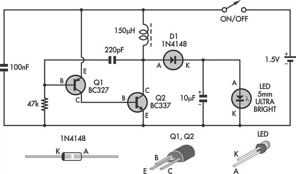
This simple LED torch is driven by a 2-transistor blocking oscillator that steps up the voltage from a 1.5V cell. It relies on the inherent current limiting of the 150 µH choke to protect the white LED from overdrive....