
High Current Low Dropout Voltage Regulator

The circuit utilizes a linear voltage regulation approach, leveraging the properties of MOSFETs to ensure stable output voltage despite variations in input conditions. The primary component, Q4, acts as the main regulator, controlling the voltage delivered to the laptop. The use of a 100kΩ resistor to drive the gate of Q4 ensures that the MOSFET remains in the appropriate operational region, providing effective regulation.
The feedback mechanism is crucial for maintaining the desired output voltage. ZD1, a zener diode, serves as a reference voltage source. When the output voltage approaches the zener voltage, Q2 is triggered, which activates Q3 to lower the gate voltage of Q4, thereby reducing the output voltage. This negative feedback loop ensures that the output remains stable at 12.4V under varying load conditions.
For applications requiring precise voltage levels, careful selection of ZD1 is essential. The recommendation to choose a zener with a voltage rating at least 0.4V lower than the output voltage allows for fine-tuning through the addition of a series resistor. This design consideration ensures that the circuit can accommodate slight variations in output voltage requirements without compromising performance.
The inclusion of ZD2 is a protective measure, ensuring that the gate-source voltage of Q4 does not exceed its rated limits, which could otherwise lead to MOSFET failure. The reverse polarity protection provided by Q1 is critical in preventing damage to the circuit in case of incorrect power supply connections.
Thermal management is addressed by requiring a heatsink for Q4, as the linear regulation process can lead to significant power dissipation, especially under maximum load conditions. The design anticipates a worst-case scenario where Q4 may dissipate up to 10W, necessitating proper thermal management to maintain reliability and efficiency.
In summary, this circuit effectively integrates several key components and design strategies to create a reliable power supply for a laptop from a solar power setup, ensuring stable operation, precise voltage regulation, and necessary protection against common electrical faults.This circuit was designed to allow a laptop computer to be powered from a solar power setup. The computer requires 12V at 3. 3A. The circuit is a linear regulator with Mosfet Q4 as the series pass device. A 100kO resistor provides Q4 with a positive gate-source voltage. Any tendency for the output voltage to exceed ZD1s voltage causes Q2 to turn on . This turns on Q3 which reduces Q4s gate voltage and thus reduces the output voltage. Note that Q2s base-emitter voltage stabilizes at about 0. 35V. This combined with the zener voltage gives an output of 12. 4V. If a more precise output is required, first select ZD1 so that its voltage rating is at least 0. 4V less than the required output voltage. You can then "trim" to the required output voltage by installing a resistor in series with ZD1. Q2s base-emitter voltage and the 680W base resistor set the current through ZD1 to 0. 5mA. This means that the output voltage will be boosted by 0. 1V for each 200O of resistance in series with ZD1. Zener diode ZD2 ensures that Q4s maximum rated gate-source voltage is not exceeded. Mosfet Q1 provides reverse polarity protection. Note that Q4 requires a heatsink since it will dissipate about 10W under worst-case conditions. No heatsink is required for Q1. At 3. 3A, the regulator reduces the output voltage by just 0. 2V. This can be further reduced by paralleling Q1 & Q4 with additional Mosfets. 🔗 External reference
Related Circuits
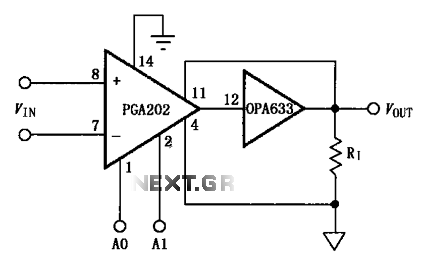
The figure illustrates a current boosting circuit configuration utilizing the PGA202 and OPA633 operational amplifiers. This circuit enhances the output current capability of the PGA202 operational amplifier, leveraging the performance characteristics of the OPA633 to achieve a higher output...
This circuit is beneficial for applications where a load must be activated from one location and deactivated from another. Multiple momentary normally open (N/O) switches or push buttons can be connected in parallel. The circuit described facilitates remote control of...
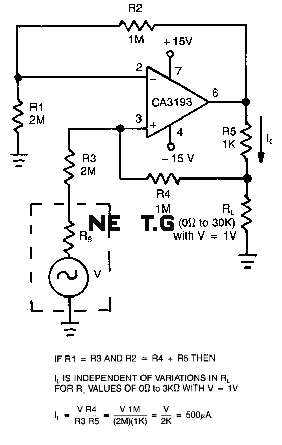
This circuit employs a CA3193 precision operational amplifier to provide a current that remains consistent regardless of variations in the load resistance (RL). By configuring the input resistance (RI) to be equal to resistance R3 and setting resistance R2...
The power-supply controller features staggered voltage-output sequencing. Four voltage outputs are activated simultaneously for voltage tracking; two outputs are designated for core and I/O supplies during power-up, while the other two outputs cater to line driver supplies where tracking...
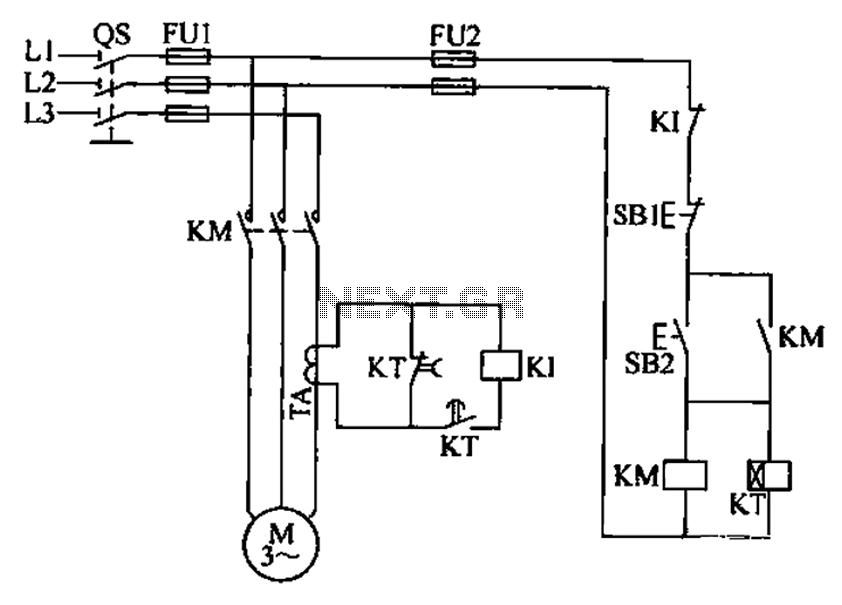
A three-phase electric motor overcurrent protection circuit. This example circuit utilizes a transformer to monitor the current, ensuring that the currents in the three-phase motor do not exceed normal operating levels. When the current exceeds the set threshold, the...
The transformer has a 240V primary and has a secondary rated 24V at 2A. The bridge rectifier contains 4 diodes, their current rating needs to be high with respect to the transformers output current; if not the current may...